
Hey Guys.
I'm going to get my finger out and wire up my thermo fans with an auto switch in the top tank. I'm not going ot use the davies craig ones in the hose, ive got one welded into the top tank already.
How i want to wire it.....
Direct power from the back of the altenator to the fans.
-ve wire to a relay.
Switch triggers the relay.
Power To the switch to come from an ignition switched source in the cabin so the fans cant run when the engine is off. (Could back feed from the battery via the back of the altenator)
Override switch in the cabin to trigger the fans to be full on incase of high temps
A second setup exactly the same MIGHT be used if i decide to go for a trans cooler with a thermo fan in front of the radiator. the trans cooler comes with a built in switch to trigger it's fan.
Can anyone see any problems with my theory?
I want to take power from the altenator connection so as to shorten the length of cable needed and not have the big draw of the fans run up through the interior, then back out to the fans as it currently is. ( pardon the pun).
Cheers!

Thermo Fan Wiring
Started by
Tiny
, Jul 25 2008 04:54 PM
91 replies to this topic
#1

Tiny
-
- Administrators
-

- 10,018 posts
Oh My, Don't you post alot
- Name:Tiny
- Location:Sydney
- Joined: 04-February 07
Posted 25 July 2008 - 04:54 PM
#2
TerrA LX
-

- Members
-
- 14,241 posts
Fulcrum Fixture
- Location:Sid 'n' knee
- Joined: 31-May 06
Posted 25 July 2008 - 05:58 PM
Found this one for single speed fans
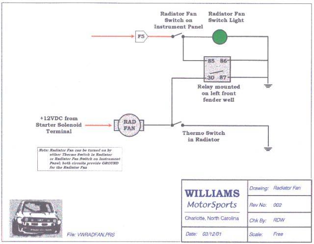
IMO run a fused 12V power supply from the starter.
Two speed is a bit more complicated.
EDIT, can we stick this in the wiki please?
IMO run a fused 12V power supply from the starter.
Two speed is a bit more complicated.
EDIT, can we stick this in the wiki please?
Edited by ALX76, 25 July 2008 - 06:08 PM.
#3
_The Baron_
_The Baron_
-

- Guests
Posted 25 July 2008 - 06:12 PM
That cct will put all the fan motor current trough the temp switch. Check the rating on the switch.
#4
Tiny
-
- Administrators
-
- 10,018 posts
Oh My, Don't you post alot
- Name:Tiny
- Location:Sydney
- Joined: 04-February 07
Posted 25 July 2008 - 06:46 PM
That cct will put all the fan motor current trough the temp switch. Check the rating on the switch.
That's what i was concerned about!
That's why i was thinking of a wire direct from altenator - through a circuit breaker - to the fan... Then the -ve of the fan pulled in by a relay... and the relay switched by the thermo switch.
I might have to try and do a ms paint schematic

Cheers!
#5
antelopeslr5000
-

- Members
-
- 1,022 posts
Forum Fixture
- Location:Toowoomba, Queensland
- Car:1977 LX SL/R 5000
- Joined: 10-November 05
Posted 25 July 2008 - 07:29 PM
Hi Tiny,
This is how I've wired my thermo fan.
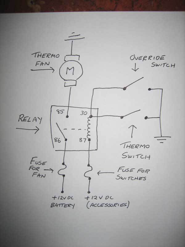
This is how I've wired my thermo fan.
#6
antelopeslr5000
-
- Members
-
- 1,022 posts
Forum Fixture
- Location:Toowoomba, Queensland
- Car:1977 LX SL/R 5000
- Joined: 10-November 05
Posted 25 July 2008 - 07:58 PM
I don't think the numbering of my relay drawing is correct but you get the general idea! 
Number 30 should be 86 and vise versa.
Number 87 should be 85 and vise versa.
Number 30 should be 86 and vise versa.
Number 87 should be 85 and vise versa.
Edited by antelopeslr5000, 25 July 2008 - 08:03 PM.
#7
_SS Hatchback_
_SS Hatchback_
-
- Guests
Posted 25 July 2008 - 08:13 PM
Hey Tiny , just remember and inline fuse from the alt to the relay which powers the fan, the hand drawing above is ok but like was mentioned the numbers could be wrong . The switch parallel to the temp sensor is good incase of failure of the sensor also like you said if you want to keep them on all the time for some reason
#8
Tiny
-
- Administrators
-
- 10,018 posts
Oh My, Don't you post alot
- Name:Tiny
- Location:Sydney
- Joined: 04-February 07
Posted 26 July 2008 - 07:11 PM
Thanks gents!
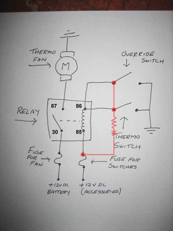
I've had a think about that layout antelope... Would you mind taking a look at my theory shown below to see if i've stuffed up?
Basically i wanted to switch the -ve side of the fans.. I'm told that this is nicer to the relay than switching the power side ( I dont see how in DC... the current still needs to be switched through the relay .. so it'll need to be a BIG relay!).
Also ive included an LED indicator to show when the fans are running (thermo switched OR overridden).
Can you guys see any mistakes in my plan?
Thanks too Rob! I'll definitely check out the relay's wiring before i hook anything up, and the override is a must!
If i end up with a trans cooler with fan then i'm going to duplicate the relay, but use the override switch to activate both the radiator and trans fans.
Thanks Guys!
#9
_SS Hatchback_
_SS Hatchback_
-
- Guests
Posted 26 July 2008 - 07:40 PM
The temp switch only has 1 connection point and is usually a switched earth so it wont work as you have drawn it as it would need 2 wires power in then switched out. Use the method that ant had to turn on the relay, has one wire coming from the sensor and then when it reaches a certain temp it switches top earth via the body of the switch.. So have 12v accessories going to the coil of the relay the switch the earth or neg side . Also the relay should probably be a 30amp relay .
The LED wont work like how you have drawn it as once the relay pics up you will you will have the negative or earth at both ends, so again use ants method switch the 12v. The 12v going to the fan should also run to the LED but you should run a resistor ( I think 560ohms) in series with it otherwise you will blow the LED unless its a 12v lamp that you run instead. If your running a LED let me know and ill figure out what size it is for sure but like i said i think from mem its around 560 Ohms.
The LED wont work like how you have drawn it as once the relay pics up you will you will have the negative or earth at both ends, so again use ants method switch the 12v. The 12v going to the fan should also run to the LED but you should run a resistor ( I think 560ohms) in series with it otherwise you will blow the LED unless its a 12v lamp that you run instead. If your running a LED let me know and ill figure out what size it is for sure but like i said i think from mem its around 560 Ohms.
#10
antelopeslr5000
-
- Members
-
- 1,022 posts
Forum Fixture
- Location:Toowoomba, Queensland
- Car:1977 LX SL/R 5000
- Joined: 10-November 05
Posted 26 July 2008 - 08:01 PM
560 ohms is good for a LED with 2.0V forward voltage (20mA).
#11
antelopeslr5000
-
- Members
-
- 1,022 posts
Forum Fixture
- Location:Toowoomba, Queensland
- Car:1977 LX SL/R 5000
- Joined: 10-November 05
Posted 26 July 2008 - 08:58 PM
I've altered my original schematic (hopefully the relay numbering is correct now!) and also included a LED which indicates when the fan is on (I'm assuming that's what you want the LED for Tiny?).
The way you had the LED wired, when the relay contacts are in the open (relaxed) position, you still have an earth path from your +12VDC source (battery) through the thermo fan and LED. I'm thinking that the LED wouldn't have like that!
The way you had the LED wired, when the relay contacts are in the open (relaxed) position, you still have an earth path from your +12VDC source (battery) through the thermo fan and LED. I'm thinking that the LED wouldn't have like that!
#12
_SS Hatchback_
_SS Hatchback_
-
- Guests
Posted 26 July 2008 - 09:05 PM
ant , that looks good however i think the LED should be fed from 87 the same as the fan, the way you have drawn it will let you know if the sender or the over ride switch is turned on but if the relay fails the light will be still on, if its connected to the 87 terminal then you know that power is getting to the fan, hope that makes sense
#13
antelopeslr5000
-
- Members
-
- 1,022 posts
Forum Fixture
- Location:Toowoomba, Queensland
- Car:1977 LX SL/R 5000
- Joined: 10-November 05
Posted 26 July 2008 - 09:28 PM
ant , that looks good however i think the LED should be fed from 87 the same as the fan, the way you have drawn it will let you know if the sender or the over ride switch is turned on but if the relay fails the light will be still on, if its connected to the 87 terminal then you know that power is getting to the fan, hope that makes sense
Yes, very good point!
#14
Tiny
-
- Administrators
-
- 10,018 posts
Oh My, Don't you post alot
- Name:Tiny
- Location:Sydney
- Joined: 04-February 07
Posted 26 July 2008 - 10:39 PM
You blokes rock!
Its a bit late now and i cant follow what was said.. but i get the picture! Thanks!
Your right about the LED, I wanted an indicator for when the fan was running, and i realised i would need a resistor too, but i had no idea about the size resitor i'd need!
Thanks again guys, I'll re-read this tomorrow and think it through!
Cheers
#15
antelopeslr5000
-
- Members
-
- 1,022 posts
Forum Fixture
- Location:Toowoomba, Queensland
- Car:1977 LX SL/R 5000
- Joined: 10-November 05
Posted 26 July 2008 - 10:47 PM
Third time's a charm!
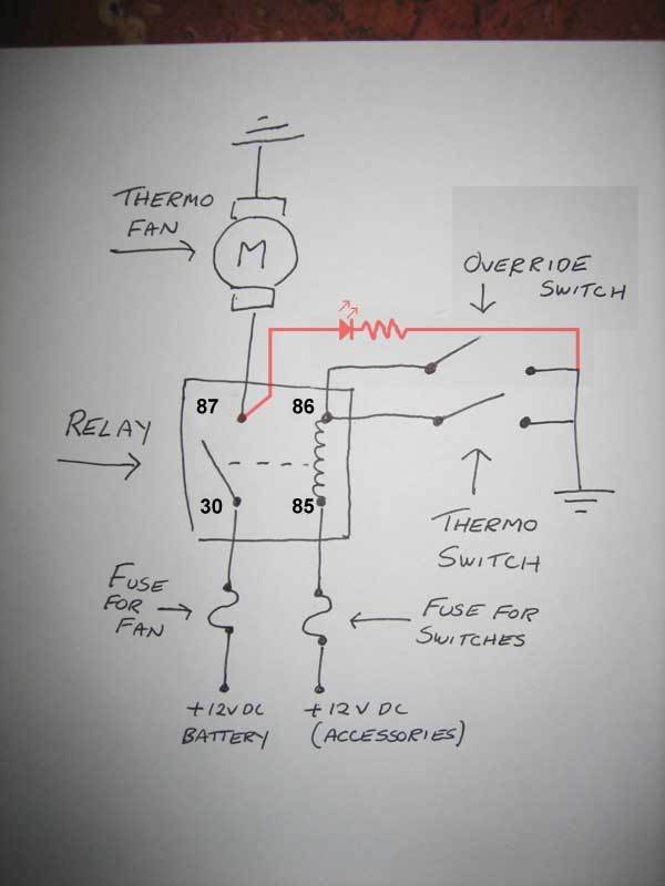
The only problem I can foresee with this schematic is if the fan does suffer a failure which doesn't blow the fuse and the relay contacts are closed, the LED will still illuminate. However, it is better than my second effort!
The only problem I can foresee with this schematic is if the fan does suffer a failure which doesn't blow the fuse and the relay contacts are closed, the LED will still illuminate. However, it is better than my second effort!
#16
_SS Hatchback_
_SS Hatchback_
-
- Guests
Posted 26 July 2008 - 11:33 PM
Thats true but there is nothing more you can do besides getting out and checking to see if fan is working, if the lights on and your car starts to run hot check your fan to see if its working if not , then your fan is knackered because its will be obvious that the relay and circuit are working. Not much more you can do .Third time's a charm!
The only problem I can foresee with this schematic is if the fan does suffer a failure which doesn't blow the fuse and the relay contacts are closed, the LED will still illuminate. However, it is better than my second effort!
Print that diagram out Tiny , thats the one
#17
LX2DR
 View Garage
-

- Members
-
- 1,763 posts
Forum Fixture
- Name:Paul
- Location:Melbourne
- Joined: 21-November 05
View Garage
Posted 26 July 2008 - 11:51 PM
I have one reservation here.
The wiring as it is, will run until the cooling effect from the fans cools the water in the radiator (Pump isn't running) & into the top hose or wherever the thermofeeler is placed.
This has the potential to flatten the battery.
I have my relay power coming from the alternator D+ terminal , not from a continuous 12V supply.
Using the D+ terminal will only allow the fans to run when the engine is running which is also circulating the water.
Simply, If the alternator isn't turning theirs no power to switch the relay's on.
You could still add an overide switch but it's still a little pointless as you will only cool the water in the radiator not the engine.
I have found with mine if i leave the car running for little while at idle and the fan running it will cool the entire system and then i shut it off.
My 2 cents worth
Paul
Edited by LX2DR, 26 July 2008 - 11:54 PM.
#18
_SS Hatchback_
_SS Hatchback_
-
- Guests
Posted 27 July 2008 - 12:00 AM
I have one reservation here.
The wiring as it is, will run until the cooling effect from the fans cools the water in the radiator (Pump isn't running) & into the top hose or wherever the thermofeeler is placed.
This has the potential to flatten the battery.
I have my relay power coming from the alternator D+ terminal , not from a continuous 12V supply.
Using the D+ terminal will only allow the fans to run when the engine is running which is also circulating the water.
Simply, If the alternator isn't turning theirs no power to switch the relay's on.
You could still add an overide switch but it's still a little pointless as you will only cool the water in the radiator not the engine.
I have found with mine if i leave the car running for little while at idle and the fan running it will cool the entire system and then i shut it off.
My 2 cents worth
Paul
By that circuit once the ignition switch is turned of the fans will turn off, although the fan is connected to constant 12v via the relay the contact will be open when ignition is off therefore wont run and flatten the battery.
The over ride switch is more for when Tiny is at an event and not moving much at all , rather than have the sensor swiotch the fans on and off all the time he will just turn then fans on constantly .
#19
LX2DR
View Garage
-
- Members
-
- 1,763 posts
Forum Fixture
- Name:Paul
- Location:Melbourne
- Joined: 21-November 05
View Garage
Posted 27 July 2008 - 12:45 AM
Whoops! my bad, the word assessory is a give-away 
I tried to make mine idiot proof so it can never be left running when kids are sitting in car listening to the radio.
It's just another option Tiny can take into consideration.
I tried to make mine idiot proof so it can never be left running when kids are sitting in car listening to the radio.
It's just another option Tiny can take into consideration.
#20
_SS Hatchback_
_SS Hatchback_
-
- Guests
Posted 27 July 2008 - 04:46 PM
and a good option it is for that reasonso it can never be left running when kids are sitting in car listening to the radio.
It's just another option Tiny can take into consideration.
#21
_torbirdie_
_torbirdie_
-
- Guests
Posted 28 July 2008 - 06:41 AM
Correct me if Im wrong, but Im guessing that tiny is using the alternator terminal as the battery is in the boot?I have my relay power coming from the alternator D+ terminal , not from a continuous 12V supply.
Using the D+ terminal will only allow the fans to run when the engine is running which is also circulating the water.
Simply, If the alternator isn't turning theirs no power to switch the relay's on.
Provided he is using the terminal that is connected directly to the battery, that terminal will get 12V whether the alternator is spinning or not.
I do have some reservations about switching the -ve supply.
This means that the +ve feed to the fans is constantly live and any accidental connection of the -ve lead of the fans to earth will trigger the fans, or accidental contact of the +ve to earth at other times, while working on the car etc.
While it makes no difference to the fundamental operation, wherever possible relays should isolate the system from 12V.
It also makes earthing of the fans more straightforward, though of course if the relays are put in the +ve side the wiring is more complex there.
For additional safety, also consider putting in a device that will shut off power to the fans if the engine isnt running(as for electric fuel pumps or lpg solenoids), as the wiring is at present the fans will run solely if the ignition is switched on.
Another consideration with your trigger wire is to not have it activated when the starter is used, as for a hot start providing another possible 40A for the fans is an extra load that might mean the difference between with a successful start
Edited by torbirdie, 28 July 2008 - 06:55 AM.
#22
REDA9X
-

- Inactive
-
- 0 posts
Removed
- Joined: 08-November 05
Posted 28 July 2008 - 04:44 PM
The original setup in my current Torana and the last was like this
Positive power from the Alternator to a relay.
Switching power from ignition to the relay so the fan would only run with ignition on. This then goes out to the fan.
Earth going to the switch in the top tank from the relay, and the fan is earthed
So with ignition on and the temperature reaching the set degree, the fan comes on. I overide this by splicing in another wire to the earth wire going to the top tank. From this wire I run to a switch under the dash and to earth, this allows manual override for when I know I'll be in traffic.
#23
_SS Hatchback_
_SS Hatchback_
-
- Guests
Posted 28 July 2008 - 06:08 PM
The original setup in my current Torana and the last was like this
Positive power from the Alternator to a relay.
Switching power from ignition to the relay so the fan would only run with ignition on. This then goes out to the fan.
Earth going to the switch in the top tank from the relay, and the fan is earthed
So with ignition on and the temperature reaching the set degree, the fan comes on. I overide this by splicing in another wire to the earth wire going to the top tank. From this wire I run to a switch under the dash and to earth, this allows manual override for when I know I'll be in traffic.
Yep thats pretty much how antelopes last picture or circuit is drawn, and mine is hooked up the same way . Just make sure you have a inline fuse between your relay and your alternator supply.
#24
REDA9X
-
- Inactive
-
- 0 posts
Removed
- Joined: 08-November 05
Posted 28 July 2008 - 06:14 PM
Yep thats pretty much how antelopes last picture or circuit is drawn, and mine is hooked up the same way . Just make sure you have a inline fuse between your relay and your alternator supply.
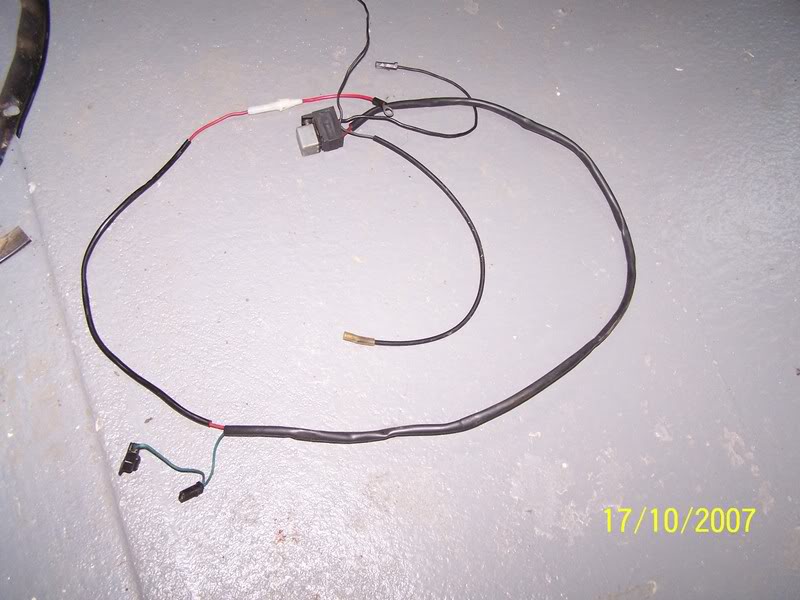
Yes, i agree there, I think I have a pic of the original harness


0 user(s) are reading this topic
0 members, 0 guests, 0 anonymous users

