
Thats it, ive have seen many times people get the supply from one of the ignition fuses for the coil side of the relay and think that the whole circuit is protected. It can catch the best of us when we are in a hurry trying to finish something.

Thermo Fan Wiring
Started by
Tiny
, Jul 25 2008 04:54 PM
91 replies to this topic
#26
 _SS Hatchback_
_SS Hatchback_
-

- Guests
Posted 28 July 2008 - 06:34 PM
#27
antelopeslr5000
-

- Members
-

- 1,022 posts
Forum Fixture
- Location:Toowoomba, Queensland
- Car:1977 LX SL/R 5000
- Joined: 10-November 05
Posted 29 July 2008 - 05:49 PM
Not 100% correct. For the fan to run, either the over ride switch and/or the thermo switch needs to be closed. It will not run solely if the ignition is switched on. However I can see your point. If the engine is at a temperature that will close the the thermo switch then placing the ignition switch in the "ON" position (or "ACC" position) will trigger the fan. If you wanted you could power a relay solenoid from the D+ output of the alternator (the point from the alternator that also supplies voltage to the alternator warning lamp) so that the realy is only energised when the alternator is running AND servicable. If the alternator fails then you'll have the possibility of losing the thermo fan also. It would probably be a good idea to have an over ride switch in this scenario.For additional safety, also consider putting in a device that will shut off power to the fans if the engine isnt running(as for electric fuel pumps or lpg solenoids), as the wiring is at present the fans will run solely if the ignition is switched on.
To my knowledge the Torana ignition switch has 5 positions.Another consideration with your trigger wire is to not have it activated when the starter is used, as for a hot start providing another possible 40A for the fans is an extra load that might mean the difference between with a successful start
1. "ACC"
2. "LOCK"
3. "OFF"
4. "ON"
5. "START"
With the ignition switch in the "START" position (i.e. engine cranking via the starter motor) power to systems connected via the "ACC" supply do not have voltage, only systems connected to the "ON" & "START" supplies do. As the relay is energised via power from the "ACC" supply, the relay contacts will be in the open position during engine starting and no power will be supplied to the fan. That's my understanding of how the "ACC" supply works. Please feel free to correct me if I'm wrong.
#28
_SS Hatchback_
_SS Hatchback_
-
- Guests
Posted 29 July 2008 - 06:31 PM
That would be ideal setup , and it wouldnt be hard to find out . Use a tester and see which fuse loses power while cranking. Hope your not too confused TinyWith the ignition switch in the "START" position (i.e. engine cranking via the starter motor) power to systems connected via the "ACC" supply do not have voltage, only systems connected to the "ON" & "START" supplies do. As the relay is energised via power from the "ACC" supply, the relay contacts will be in the open position during engine starting and no power will be supplied to the fan. That's my understanding of how the "ACC" supply works. Please feel free to correct me if I'm wrong.

#29
_torbirdie_
_torbirdie_
-
- Guests
Posted 30 July 2008 - 01:01 AM
Not 100% correct. For the fan to run, either the over ride switch and/or the thermo switch needs to be closed. It will not run solely if the ignition is switched on. However I can see your point. If the engine is at a temperature that will close the the thermo switch then placing the ignition switch in the "ON" position (or "ACC" position) will trigger the fan.
Sorry, I see the confusion, yes I was meaning to say that solely having the ignition on will have the fan circuit active. There is the risk that if the motor stops for whatever reason and someone is poking around under the bonnet to see what is wrong that the fans may trigger in this situation, temp at the switch can easily get very high soon after switch off. We also dont want anything getting electrically switched in the event of an accident either, when fuel is around.
If you wanted you could power a relay solenoid from the D+ output of the alternator (the point from the alternator that also supplies voltage to the alternator warning lamp) so that the realy is only energised when the alternator is running AND servicable. If the alternator fails then you'll have the possibility of losing the thermo fan also. It would probably be a good idea to have an over ride switch in this scenario.
Hadn't thought about doing that, wouldnt that make all the vac switches etc switches totally unnecessary?
Are you sure that it would work?
your description of the alternator supplying voltage to the warning lamp leaves me with some doubt as to whether you know what you are talking about?(most likely you do, but you have been a little careless with that statement?) I was under the impression that the brown wire to the alternator provided 12V to the alternator and that without it the alternator wouldnt charge properly, the field wires would not initially be energised, and that the glow of the alternator lamp is due to the 12V coming from the instrument panel to the lamp and being earthed through the field wires.
It is correct though, that when the ignition is switched off and the engine continues to run( a rare situation), current will then run from the D+ terminal to the lamp and be earthed through the other instruments.
I havent done any measuring on this terminal, but would like to check that the voltage on the D+ terminal drops to a value of less than 3V when the engine stops running with the ign switched on, any higher than this and we might not deactivate/activate the relay
To my knowledge the Torana ignition switch has 5 positions.
1. "ACC"
2. "LOCK"
3. "OFF"
4. "ON"
5. "START"
With the ignition switch in the "START" position (i.e. engine cranking via the starter motor) power to systems connected via the "ACC" supply do not have voltage, only systems connected to the "ON" & "START" supplies do. As the relay is energised via power from the "ACC" supply, the relay contacts will be in the open position during engine starting and no power will be supplied to the fan. That's my understanding of how the "ACC" supply works. Please feel free to correct me if I'm wrong.
This is correct, and i have said nothing to contradict that.
The feed wire should be connected to the accessory supply which will die when the starter is cranked, but many mention just connecting it to the ignition, which I take to mean whatever is supplying the coil.
Edited by torbirdie, 30 July 2008 - 01:07 AM.
#30
_torbirdie_
_torbirdie_
-
- Guests
Posted 30 July 2008 - 01:22 AM
Moderators, can you please delete the post of mine ^, i got timed out on the edit!
Sorry, I see the confusion, yes I was meaning to say that solely having the ignition on will have the fan circuit active. There is the risk that if the motor stops for whatever reason and someone is poking around under the bonnet to see what is wrong that the fans may trigger in this situation, temp at the switch can easily get very high soon after switch off. We also dont want anything getting electrically switched in the event of an accident either, when fuel is around.
Hadn't thought about doing that, wouldnt that make all the vac switches etc switches totally unnecessary?
Actually, now I read back on lx2drs post, that's exactly what he has set up.....and I told him it wouldnt work......I was thinking of the B+ terminal, sorry about that lx2dr.
but antelope: your description of the alternator supplying voltage to the warning lamp is perhpas a little careless?
I was under the impression that the brown wire to the alternator provided 12V to the alternator and that without it the alternator wouldnt charge properly, the field wires would not initially be energised, and that the glow of the alternator lamp is due to the 12V coming from the instrument panel to the lamp and being earthed through the field wires.
It is correct though, that when the ignition is switched off and the engine continues to run( a rare situation), current will then run from the D+ terminal to the lamp and be earthed through the other instruments.
This is correct, and i have said nothing to contradict that.
The feed wire should be connected to the accessory supply which will die when the starter is cranked, but many mention just connecting it to the ignition, which I take to mean whatever is supplying the coil, and yes I see that in your sketch you specifically mention the accessory connection.
Not 100% correct. For the fan to run, either the over ride switch and/or the thermo switch needs to be closed. It will not run solely if the ignition is switched on. However I can see your point. If the engine is at a temperature that will close the the thermo switch then placing the ignition switch in the "ON" position (or "ACC" position) will trigger the fan.
Sorry, I see the confusion, yes I was meaning to say that solely having the ignition on will have the fan circuit active. There is the risk that if the motor stops for whatever reason and someone is poking around under the bonnet to see what is wrong that the fans may trigger in this situation, temp at the switch can easily get very high soon after switch off. We also dont want anything getting electrically switched in the event of an accident either, when fuel is around.
If you wanted you could power a relay solenoid from the D+ output of the alternator (the point from the alternator that also supplies voltage to the alternator warning lamp) so that the realy is only energised when the alternator is running AND servicable. If the alternator fails then you'll have the possibility of losing the thermo fan also. It would probably be a good idea to have an over ride switch in this scenario.
Hadn't thought about doing that, wouldnt that make all the vac switches etc switches totally unnecessary?
Actually, now I read back on lx2drs post, that's exactly what he has set up.....and I told him it wouldnt work......I was thinking of the B+ terminal, sorry about that lx2dr.
but antelope: your description of the alternator supplying voltage to the warning lamp is perhpas a little careless?
I was under the impression that the brown wire to the alternator provided 12V to the alternator and that without it the alternator wouldnt charge properly, the field wires would not initially be energised, and that the glow of the alternator lamp is due to the 12V coming from the instrument panel to the lamp and being earthed through the field wires.
It is correct though, that when the ignition is switched off and the engine continues to run( a rare situation), current will then run from the D+ terminal to the lamp and be earthed through the other instruments.
To my knowledge the Torana ignition switch has 5 positions.
1. "ACC"
2. "LOCK"
3. "OFF"
4. "ON"
5. "START"
With the ignition switch in the "START" position (i.e. engine cranking via the starter motor) power to systems connected via the "ACC" supply do not have voltage, only systems connected to the "ON" & "START" supplies do. As the relay is energised via power from the "ACC" supply, the relay contacts will be in the open position during engine starting and no power will be supplied to the fan. That's my understanding of how the "ACC" supply works. Please feel free to correct me if I'm wrong.
This is correct, and i have said nothing to contradict that.
The feed wire should be connected to the accessory supply which will die when the starter is cranked, but many mention just connecting it to the ignition, which I take to mean whatever is supplying the coil, and yes I see that in your sketch you specifically mention the accessory connection.
#31
antelopeslr5000
-
- Members
-
- 1,022 posts
Forum Fixture
- Location:Toowoomba, Queensland
- Car:1977 LX SL/R 5000
- Joined: 10-November 05
Posted 30 July 2008 - 04:50 PM
your description of the alternator supplying voltage to the warning lamp leaves me with some doubt as to whether you know what you are talking about
Yeah, fair call, I probably don't know what I'm talking about!

However, I'll stand by what I said about the warning lamp being supplied with voltage from the alternator when it's running and servicable. When the alternator is running in a servicable condition you'll have 12V supplied from the instrument panel to one side of the warning lamp and 12V supplied from the alternator to the other side of the warning lamp. With equal potential of 12V on both sides of the warning lamp, the warning lamp is extinguished.
#32
Tiny
-
- Administrators
-
- 10,018 posts
Oh My, Don't you post alot
- Name:Tiny
- Location:Sydney
- Joined: 04-February 07
Posted 30 July 2008 - 07:41 PM
That would be ideal setup , and it wouldnt be hard to find out . Use a tester and see which fuse loses power while cranking. Hope your not too confused Tiny
I AM!! LOL!
Actually i'm reading (And re-reading) the posts, and i think i'm seeing the theories behind what's being said!
I am concerned about torbirdie's comment about the fans triggering on startup if the radiator is hot because that is a situation my car often finds.
I wonder whether antelope is right in that the relay would be open when cranking? I'd really like to save those 30-40A for the starter!
And correct torbirdie, i'm using the D+ terminal as a junction because my battery is boot mounted, and via the main wire of the starter being the junction for the power from the D+; the rest of the car; the main battery lead, the D+ terminal will always be 12V Live.
Thanks again guys.. It's not something i'm doing tomorrow.. i just wanted to get everything sorted so that when i do attack it i know it's going to work!
The consensus at the moment is: The last image posted by Antelope is the best version to use?
Thanks again! I think this topic will be helpful in the future for many people! I guess were trying to derive the "best" way of doing this!
#33
antelopeslr5000
-
- Members
-
- 1,022 posts
Forum Fixture
- Location:Toowoomba, Queensland
- Car:1977 LX SL/R 5000
- Joined: 10-November 05
Posted 30 July 2008 - 07:50 PM
Do you have an oil pressure switch or an oil pressure sender Tiny? If you have an oil pressure switch you could use that to help control a relay for fan operation when the engine is running (providing you have correct oil pressure of course!).
#34
Tiny
-
- Administrators
-
- 10,018 posts
Oh My, Don't you post alot
- Name:Tiny
- Location:Sydney
- Joined: 04-February 07
Posted 30 July 2008 - 07:57 PM
I've got an oil pressure sender, but i've been meaning to install a switch too to trigger a buzzer and light in cabin at low pressure!
The problem is... if i crank it for > 10 seconds.. i have > 20Psi oil pressure!! (Yep.. serious oil pump!!) SO i think that's going to play havoc with my pressure switch unless i get a relatively high ( 30Psi??) set switch.
Maybe a tachiometric relay might be better to read ignition pulses?
Cheers!
The problem is... if i crank it for > 10 seconds.. i have > 20Psi oil pressure!! (Yep.. serious oil pump!!) SO i think that's going to play havoc with my pressure switch unless i get a relatively high ( 30Psi??) set switch.
Maybe a tachiometric relay might be better to read ignition pulses?
Cheers!
#35
_SS Hatchback_
_SS Hatchback_
-
- Guests
Posted 30 July 2008 - 08:11 PM
you could really make the circuit overcomplicated , the last drawing is a very good example and thanks Ant for continuously drawing it to help show what we were talking about. The acc should turn off while cranking so you will save the 30-40a for starting.
Torbirdie, yep i meant to say acc not ign.
Torbirdie, yep i meant to say acc not ign.
#36
antelopeslr5000
-
- Members
-
- 1,022 posts
Forum Fixture
- Location:Toowoomba, Queensland
- Car:1977 LX SL/R 5000
- Joined: 10-November 05
Posted 30 July 2008 - 09:52 PM
Well, this is what I had in mind with regards to the oil pressure switch control.
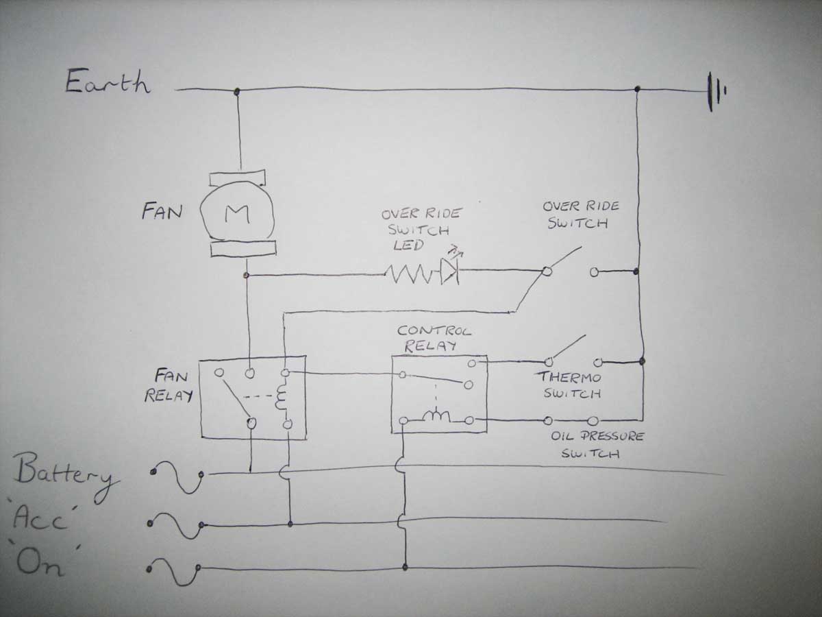
The schematic shows the ignition switch in the �ON� position, the engine not running, engine temperature below the threshold for activation of the Thermo Switch and the Over Ride Switch in its OFF position.
In this scenario, the Oil Pressure Switch will be closed (no oil pressure) and the Control Relay solenoid will be energised. With the Control Relay energised the Fan Relay solenoid has no earth path and the Fan Relay cannot be energised. No power will be applied to the Fan with the Fan Relay in the relaxed state.
When the ignition switch is moved to the �START� position the �ACC� supply is lost, the Fan Relay cannot be energised and no power will be applied to the Fan during the start phase (regardless of the state of the Control Relay, Thermo Switch, Oil Pressure Switch or Over Ride Switch positions).
Once the engine is running, the oil pressure switch will open (provided that there is sufficient oil pressure), the Control Relay solenoid now has no earth path and the Control Relay will return to its relaxed state. In its relaxed state, the Fan Relay solenoid now has a path (through the Control Relay) to the Thermo Switch.
Once the operating temperature of the Thermo Switch is reached, the Thermo Switch will close. Now the Fan Relay solenoid has an earth path (through the Control Relay and Thermo Switch) and the Fan Relay will energise. Power is now available to the Fan when the Fan Relay is energised.
Operation of the Over Ride Switch will effectively bypass the Control Relay and Thermo Switch and provide an earth path for the Fan Relay solenoid. If the ignition switch is either in the �ACC� or �ON� position and the Over Ride switch is in its ON position, the Fan Relay will energise and power will be applied to the Fan.
If your car doesn�t have a oil pressure switch then a Tachometric Relay, as Tiny has suggested, could be used to provide a similar function to that of the Control Relay.
It�s a little more complicated circuit than before but it provides the extra isolation feature of the fan if the engine isn�t running (except if the Over Ride Switch is in use).
#37
TerrA LX
-

- Members
-
- 14,241 posts
Fulcrum Fixture
- Location:Sid 'n' knee
- Joined: 31-May 06
Posted 30 July 2008 - 10:25 PM
Thats a big effort for a system that needs to be fail safe.
#38
Tiny
-
- Administrators
-
- 10,018 posts
Oh My, Don't you post alot
- Name:Tiny
- Location:Sydney
- Joined: 04-February 07
Posted 31 July 2008 - 08:30 PM
Just a bit of info on what a tachiometric relay is and how it works (VERY simple!) http://moodle.studen...Comp/tacho.html
I think it could be a good option rather than an oil pressure switch to trigger a number of items in the car that might need it... Fuel pump would be a good one!
Thanks again SS and Antelope, your help has been great! I think that last drawing has given me the inspiration i need to get it sorted.. and i think i'll find/use a tachiometric relay instead of the oil pressure switch too!
ALX: I Hope that the override switch gives me the fail safe surety as much as anything can! My worst fear is a blown fan motor or two!!
#39
TerrA LX
-
- Members
-
- 14,241 posts
Fulcrum Fixture
- Location:Sid 'n' knee
- Joined: 31-May 06
Posted 31 July 2008 - 08:38 PM
^ i was more thinking along the lines of relying on two relays etc instead of one (purpose built) switch.
but what ever makes you feel cool. (pardon the pun)
but what ever makes you feel cool. (pardon the pun)
#40
Tiny
-
- Administrators
-
- 10,018 posts
Oh My, Don't you post alot
- Name:Tiny
- Location:Sydney
- Joined: 04-February 07
Posted 31 July 2008 - 08:43 PM
hehe I do understand where your coming from mate! I've always been a fan (Yep.. pun intended!) of engine fans.. but these AU thermos are frigging awesome!
I just sort of wanted to come up with the "best" Solution cause it was a bit of a dilemma, I think we've got to the bottom of it now! i doubt there is much else we could do to make it any better!
Cheers!
I just sort of wanted to come up with the "best" Solution cause it was a bit of a dilemma, I think we've got to the bottom of it now! i doubt there is much else we could do to make it any better!
Cheers!
#41
TerrA LX
-
- Members
-
- 14,241 posts
Fulcrum Fixture
- Location:Sid 'n' knee
- Joined: 31-May 06
Posted 31 July 2008 - 08:52 PM
I feel any system can be made more reliable by a; Neg- ground switching and b; positive power supply fused via circuit breakers.
Edited by ALX76, 31 July 2008 - 08:53 PM.
#42
_ChiaLX_
_ChiaLX_
-
- Guests
Posted 29 August 2008 - 08:46 AM
I am looking to do the same thing here, as my current system is switched on manually only inside the cabin. very dangerous if you dont keep an eye on the temp gauge and turn fans on when needed.
I understand thw whole schematic that antelope drew
I have two relays at the moment. one to trigger each fan on a au setup. My question is can I run the two fans off one relay as in the drawing or trigger each fan with seperate relays.
Also what on and off temp should I look for in the thermatic switch. my car runs around 175f while driving above 80km.
#43
Tiny
-
- Administrators
-
- 10,018 posts
Oh My, Don't you post alot
- Name:Tiny
- Location:Sydney
- Joined: 04-February 07
Posted 27 December 2008 - 10:23 AM
Chia,
Sorry i didnt see this mate, But currently both my fans run from inside the cabin via 1 relay! so yes.. it does work.. but they spin relatively slowly due to the power drop.
I'm going to be replacing all of this during my dash rebuild currently underway, and the question that i had was:
Does anyone know what the current these fans draw would be? I want to use a fused relay to trigger these fans, and the fuse is 30A...
Tridon TR13: - http://www.tridon.co.......=478&P=2001
I'm considering using 2 of these fused relays to activate the fans through so 30A each.
I was hoping to use 2 off Circuit Breakers and 2 off relays to feed the fans but i could not find an enclosure big enough to house all of this crap!
Cheers Guys!
#44
ls2lxhatch
-
- Members
-
- 5,331 posts
- Location:Perth
- Car:LX Hatch
- Joined: 29-May 06
Posted 27 December 2008 - 12:19 PM
http://www.gmh-toran.......=25191&st=6I measured the current on the fans..each fan has a start up current of approx 25 to 30 amps then settle to 10A once running..hence the requirement of such a large fuse.
I plan to use a SPAL fan controller for my fans. The SPAL fan controller can be configured to read your temperature gauge sender or use a SPAL sender. When the temperature reaches the trigger temperature the SPAL controller starts the first fan at low speed. The fan speed is increased as the temperature increases. If the temperature reaches the second trigger limit then the second fan is started at full speed.
http://www.spalusa.c...ies/fanpwm.html
The failsafe method would be to wire each fan on a separate system with a trigger sensor and relay for each fan. This would also give you the ability to switch in the fans at different temperatures to reduce the startup load on the system.
#45
Tiny
-
- Administrators
-
- 10,018 posts
Oh My, Don't you post alot
- Name:Tiny
- Location:Sydney
- Joined: 04-February 07
Posted 27 December 2008 - 02:34 PM
Great info thanks for that!
Where would you buy the SPAL controller from in Australia?
Where would you buy the SPAL controller from in Australia?
#46
ls2lxhatch
-
- Members
-
- 5,331 posts
- Location:Perth
- Car:LX Hatch
- Joined: 29-May 06
Posted 28 December 2008 - 01:53 PM
I bought my SPAL fan controller about six months ago from USA eBay. I was going to purchase the controller from Browns Radiators but there were supply issues in Australia at the time. I think Browns Radiators told me that Cooldrive are the Australian distributor.
http://www.cooldrive...-locations.aspx
I purchased a SPAL fan through a REPCO store so they may be able to help.
It looks like they are up to version 3 of the controller. My controller has the harness permanently attached, the harness on the v3 controller appears to be a plug in.
http://cgi.ebay.com/...emZ200271265893
#47
Tiny
-
- Administrators
-
- 10,018 posts
Oh My, Don't you post alot
- Name:Tiny
- Location:Sydney
- Joined: 04-February 07
Posted 28 December 2008 - 02:59 PM
Thanks heaps for that info! Looks like this could save people lots of headaches!
I found all the wiring and doovie hoovies i had to build my last control box, so i'm going back to the drawing board and doing away with teh circuit breakers and just using Narva 30A relays with built in auto fuse holders, 2 off ( one to power each fan motor) inside an aluminium box for neatness and waterproofing.
One question i had for the gurus, (Antelopeslr5000 or SSHatchback might be able to illuminate me on this question!) I am going to go with the fan circuit that was devised by Antelope but NOT the oil pressure sensitive one. I'd like to wire the LED trigger on the EARTH side of the fan motors, Would this be at -ve potential or when the fans run would this have power supplied to light the LED?
Basically what i'm saying is take the red line on the last drawing from the 87 point, and put it after the motor but before the earth point. The way i was thinking this would have power there (Passed through the motor) if the motor was running, but if the motor was off, damaged (open circuit) the LED would not light. If the motor short circuited then it would blow the fuse and still the LED would not light.
Cheers!
#48
_SS Hatchback_
_SS Hatchback_
-
- Guests
Posted 30 December 2008 - 03:50 PM
I see what your saying Tiny however it would basically be like having it connected straight to earth or ground making it -ive, if you disconnect the earth or ground of the motor then you would have +ive minus whatever drop of power you get throught the windings of the fan but then your fans wouldnt work  .
.
Basically not a bad setup , if your light is on then you know your fan is getting power and your relay relay is working , however if your light is on and car is starting to overheat then you can basically say that the fan is stuffed or the cable going from the relay to fan is disconnected or broken .
Hope this helps
. Basically not a bad setup , if your light is on then you know your fan is getting power and your relay relay is working , however if your light is on and car is starting to overheat then you can basically say that the fan is stuffed or the cable going from the relay to fan is disconnected or broken .
Hope this helps
Edited by SS Hatchback, 30 December 2008 - 03:51 PM.
#49
Tiny
-
- Administrators
-
- 10,018 posts
Oh My, Don't you post alot
- Name:Tiny
- Location:Sydney
- Joined: 04-February 07
Posted 30 December 2008 - 03:58 PM
Yeah i thought about that rob! hehe Thanks mate
i Went to Jaycar today and spent my hard earned on a heap of he good gear, The car has had the dash stripped and away we go!
I'll post in my projects thread and keep you all updated
Cheers and Thanks again for all the help!
i Went to Jaycar today and spent my hard earned on a heap of he good gear, The car has had the dash stripped and away we go!
I'll post in my projects thread and keep you all updated
Cheers and Thanks again for all the help!
#50
Tiny
-
- Administrators
-
- 10,018 posts
Oh My, Don't you post alot
- Name:Tiny
- Location:Sydney
- Joined: 04-February 07
Posted 19 January 2009 - 07:50 PM
A bit of an update on how it all went.
I decided to use a single relay and fuse feeding BOTH fan motors.
The pain power comes from the altenator power terminal, and i use the temperature sender, override switch and LED like the schematic in AntelopeSLR's third drawing.
I found that using an automotive type 30A fuse was not sufficient... THe first time i fired up teh fans from in the cabin, they worked fine however with the engine running the fuse got cooked!
I replaced the fuse and tried again, and also tried letting the thermo switch bring it on but it all ended up with the same result - Blown fuse!
I put my Multimeter in line replacing the fuse and read 43.x Amps (Varied 0.1 amp here and there) on fan motor activation! - it was simply cooking those 30A fuses. The issue is only on start up as when the fans get up to speed they only draw 18.7A
I gave a 40A fuse a go, but unfortunately it could not cop the power either.
Luckily we had a glass fuse holder and was reccomended we give those a try. I put the glass fuse into the circuit to replace the Auto fuse style holder and used a 35A glass fuse and Viola! Problem solved!
Just a word of warning to those using these fans.. they draw a LOT of power on start up! If i had the room and the time again, i'd probably use one relay and one 30A fuse for EACH motor!
Cheers.


0 user(s) are reading this topic
0 members, 0 guests, 0 anonymous users

