
Hey tiny,
What Thermo fans are you using? I'm just about to hook up my AU Twin thermos... Thats interesting about the Fuse, my Davis Craig fans use to melt the 30A glass fuses as well... Not sure if it was the heat from the radiator that did it, or there was way to much power going through it... They didnt blow, they just warped and melted.
I might get two inline fuse holders and run two 30A fuses to mind the load.

Thermo Fan Wiring
Started by
Tiny
, Jul 25 2008 04:54 PM
91 replies to this topic
#51

MRLXSS
-

- Members
-

- 12,396 posts
The Render Garage
- Name:Matt
- Location:Upwey, Melbourne
- Car:355 LX Hatchback, DeLorean DMC-12, LX SS Hatch, VY Cross8 Crewman
- Joined: 09-November 05
Posted 19 January 2009 - 08:12 PM
#52
Tiny
-
- Administrators
-
- 10,018 posts
Oh My, Don't you post alot
- Name:Tiny
- Location:Sydney
- Joined: 04-February 07
Posted 19 January 2009 - 08:25 PM
Hi Matt,
Yep mate it's AU Twin Fans i'm using!
it blew the 30A and 40A fuses to smithereens in seconds, but the 35A glass fuse seems to be holding!
If i had my time again, I'd go twin 30A fuses with suitably rated wire, and twin relays - One circuit feeding each motor, but all triggered together (though you could be REALLY trick and trigger individually if you wanted!).
Remeber the high current draw is only for two or three seconds maximum and i used 50A rated wire so i'm happy!
#53
_SS Hatchback_
_SS Hatchback_
-

- Guests
Posted 19 January 2009 - 09:27 PM
Hi Matt,
Yep mate it's AU Twin Fans i'm using!
it blew the 30A and 40A fuses to smithereens in seconds, but the 35A glass fuse seems to be holding!
If i had my time again, I'd go twin 30A fuses with suitably rated wire, and twin relays - One circuit feeding each motor, but all triggered together (though you could be REALLY trick and trigger individually if you wanted!).
Remeber the high current draw is only for two or three seconds maximum and i used 50A rated wire so i'm happy!
Where did you get that wire from Tiny? (50amp) and how much was it per metre?
And i knew the current draw was high as i normally hear my 55amp alternator crying hahaha dont worry im upgrading soon

#54
Tiny
-
- Administrators
-
- 10,018 posts
Oh My, Don't you post alot
- Name:Tiny
- Location:Sydney
- Joined: 04-February 07
Posted 20 January 2009 - 04:44 PM
I bought all my gear from Keith mate, Drop him a PM and he'll be more than happy to help!
I used 3mm - 10A rated cable for most of it, triggering relays and actrivating LEDs but i used the heavy 50A 6mm cable for the high current stuff like the fans!
I've got a fair bit left on the rolls if you need some too rob!
Cheers!
I used 3mm - 10A rated cable for most of it, triggering relays and actrivating LEDs but i used the heavy 50A 6mm cable for the high current stuff like the fans!
I've got a fair bit left on the rolls if you need some too rob!
Cheers!
#55
_SS Hatchback_
_SS Hatchback_
-
- Guests
Posted 20 January 2009 - 07:41 PM
ahh very goodI bought all my gear from Keith mate, Drop him a PM and he'll be more than happy to help!
I used 3mm - 10A rated cable for most of it, triggering relays and actrivating LEDs but i used the heavy 50A 6mm cable for the high current stuff like the fans!
I've got a fair bit left on the rolls if you need some too rob!
Cheers!
I have colours blue, red, white, black, grey but may need yellow, green, orange ? Just to have a few different colours as im gonig to redo my fuse board and wiring to front end, hopefully have all relays and fuses in glovebox.
Also may be after some bigger than 50amp to be the feeder from the starter motor to the main fuse panel. Not tackling it just yet but trying to get things organised incase i get bored one day
#56
Tiny
-
- Administrators
-
- 10,018 posts
Oh My, Don't you post alot
- Name:Tiny
- Location:Sydney
- Joined: 04-February 07
Posted 20 January 2009 - 07:50 PM
Absolutely mate!
Give Keith a buzz, they can get you any colour you need!
Cheers mate!
Give Keith a buzz, they can get you any colour you need!
Cheers mate!
#57
TerrA LX
-

- Members
-
- 14,241 posts
Fulcrum Fixture
- Location:Sid 'n' knee
- Joined: 31-May 06
Posted 21 January 2009 - 02:14 PM
Im thinking 40amp should have been ample (pardon the run) but you are starting the fans at high speed.
The ford computer starts them at low speed then switches to high IF it is ever needed, which AFAIK is near never.
The factory computer can be substituted with a Tridon dual switch;
Part number: 2FS 214
Low temperature switching points: On 80 off 75 deg. C
High temperature switching points: On 87 off 82 deg. C
Thread: M22 x 1.5
#58
Tiny
-
- Administrators
-
- 10,018 posts
Oh My, Don't you post alot
- Name:Tiny
- Location:Sydney
- Joined: 04-February 07
Posted 21 January 2009 - 06:53 PM
That's an interesting one terry!
I guess i could have triggered one motor with the low temp and the second motor with the high temp if i'd have known about that one previously!
Ahh well!
I'm sure that will help others though!
I guess i could have triggered one motor with the low temp and the second motor with the high temp if i'd have known about that one previously!
Ahh well!
I'm sure that will help others though!
#59
antelopeslr5000
-

- Members
-
- 1,022 posts
Forum Fixture
- Location:Toowoomba, Queensland
- Car:1977 LX SL/R 5000
- Joined: 10-November 05
Posted 21 January 2009 - 07:01 PM
I guess i could have triggered one motor with the low temp and the second motor with the high temp if i'd have known about that one previously!
Or both fans wired in series for low speed/low temp then switch the fans to parallel (via relays) for high speed/high temp.

#60
_SS Hatchback_
_SS Hatchback_
-
- Guests
Posted 21 January 2009 - 07:02 PM
Terry that would be real handy , so what your saying is one unit with 2 connection points , The first motor would have already drawn its startup current then dropped before the other even thought about coming on and not to mention not running both fans if not needed. Nice info TIm thinking 40amp should have been ample (pardon the run) but you are starting the fans at high speed.
The ford computer starts them at low speed then switches to high IF it is ever needed, which AFAIK is near never.
The factory computer can be substituted with a Tridon dual switch;
Part number: 2FS 214
Low temperature switching points: On 80 off 75 deg. C
High temperature switching points: On 87 off 82 deg. C
Thread: M22 x 1.5
Edited by SS Hatchback, 21 January 2009 - 07:06 PM.
#61
Tiny
-
- Administrators
-
- 10,018 posts
Oh My, Don't you post alot
- Name:Tiny
- Location:Sydney
- Joined: 04-February 07
Posted 21 January 2009 - 07:04 PM
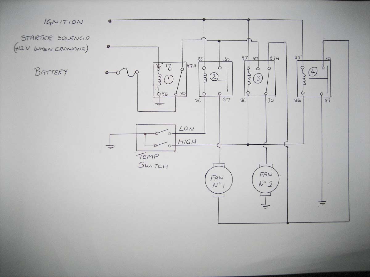
I think someone gave me a circuit diagram for that Antelope
#62
antelopeslr5000
-
- Members
-
- 1,022 posts
Forum Fixture
- Location:Toowoomba, Queensland
- Car:1977 LX SL/R 5000
- Joined: 10-November 05
Posted 21 January 2009 - 07:09 PM
I think someone gave me a circuit diagram for that Antelope
lol... Did it look something like this?
#63
Tiny
-
- Administrators
-
- 10,018 posts
Oh My, Don't you post alot
- Name:Tiny
- Location:Sydney
- Joined: 04-February 07
Posted 21 January 2009 - 07:18 PM
It did!
And i reckon he's a smart fella too!

And i reckon he's a smart fella too!
#64
TerrA LX
-
- Members
-
- 14,241 posts
Fulcrum Fixture
- Location:Sid 'n' knee
- Joined: 31-May 06
Posted 22 January 2009 - 12:46 PM
Sorry guys, sometimes I loose track of a topic.
The au ford system uses three relays but one model did use 4.
http://www.fordmods....Wiring-d54.html
The au ford system uses three relays but one model did use 4.
http://www.fordmods....Wiring-d54.html

#66
hanra
-
- Members
-
- 10,831 posts
Oh My, Don't you post alot
- Name:Brad
- Location:Farrrrrr North Qld
- Car:1975 LH SL/R 5000, 1967 Morris Cooper S, E36 BMW, Toyota Corolla, Isuzu DMax
- Joined: 24-March 11
Posted 03 June 2012 - 12:59 AM
Diggin up a very old thread...
Interesting to see in this clip the current draw at start up of these AU fans.
It peaks around 61amp for a very brief moment....
Interesting to see in this clip the current draw at start up of these AU fans.
It peaks around 61amp for a very brief moment....
#67
LJGTR6
 View Garage
-

- Members
-
- 309 posts
Forum Fan
- Name:Steve
- Location:NSW
- Car:1977 LX SL 4 Door and 1973 LJ 2 Door
- Joined: 06-April 10
View Garage
Posted 21 July 2013 - 07:34 AM
Great read being a sparky i understand the wiring. Some very good ideas.
I am having my wiring loom re-done at vintage wiring in Ringwood at the moment.
I have had an after thought while dropping it off. The car will have thermo fans.
I am going to ask him to add some signal wiring into the loom right down to beyond the head lights. (an on signal)
to run to the sensor switch to drive the relays when the ignition is on. My guess is i could hide or mount the relays down here
somewhere that would not look to bad.
My question is where did any of you get the fans MAIN 12 volts from and how did you run it and how did you
hide the fuses etc.
There is nothing worse looking in my opinion than 1 or 2 extra 4mm sq red wires running to some where that clearly
look like an after thought. Especially if you can see them.
Where did Holden get the 12 V and put the fuses in the originals (understand that this may not get answered).
I thought of getting him to run it all the way from the fuse panel but the original supply wiring to the fuse panel i would guess
is not rated to run the thermo fans
The only places i can think of is from the alternator, starter motor or directly on the battery.
What did any one here do. where did you pick this up from and make it look decent.
What would you do if you had the opportunity now with the wiring loom being made from scratch.
steve
#68
Tiny
-
- Administrators
-
- 10,018 posts
Oh My, Don't you post alot
- Name:Tiny
- Location:Sydney
- Joined: 04-February 07
Posted 21 July 2013 - 07:46 AM
G'day Steve,
I took my power feed off the back of the alternator, this was the neatest i could do, as my battery is in the boot.
The fuses are just inline but you could hide them under the guard or between the grill and rad support!
Just as a side note, the set up I had actually worked perfectly, the reason it cooked my fuse holder was I had a dickey fan motor!!!
I installed the SPAL pwm v3 controller and it brought up an error!! Over current on fan motor 1!!, we swapped the fan and viola! Perfect!! Which means why old twin relay setup
Was actually FINE! AAAAARGGGHHHHHH.......
Anyway!
All the best with it!
#69
LJGTR6
View Garage
-
- Members
-
- 309 posts
Forum Fan
- Name:Steve
- Location:NSW
- Car:1977 LX SL 4 Door and 1973 LJ 2 Door
- Joined: 06-April 10
View Garage
Posted 21 July 2013 - 07:53 PM
Cheers Rob. Glad you got your sorted.
That sounds to me like the best spot to pick up power too.
much appreciated.
steve
#70
Tiny
-
- Administrators
-
- 10,018 posts
Oh My, Don't you post alot
- Name:Tiny
- Location:Sydney
- Joined: 04-February 07
Posted 21 July 2013 - 09:50 PM
All the best mate, love to see how you go with yours!
#71
_LS1 Hatch_
_LS1 Hatch_
-
- Guests
Posted 22 July 2013 - 01:36 AM
Great read being a sparky i understand the wiring. Some very good ideas.
I am having my wiring loom re-done at vintage wiring in Ringwood at the moment.
I have had an after thought while dropping it off. The car will have thermo fans.
I am going to ask him to add some signal wiring into the loom right down to beyond the head lights. (an on signal)
to run to the sensor switch to drive the relays when the ignition is on. My guess is i could hide or mount the relays down here
somewhere that would not look to bad.
My question is where did any of you get the fans MAIN 12 volts from and how did you run it and how did you
hide the fuses etc.
There is nothing worse looking in my opinion than 1 or 2 extra 4mm sq red wires running to some where that clearly
look like an after thought. Especially if you can see them.
Where did Holden get the 12 V and put the fuses in the originals (understand that this may not get answered).
I thought of getting him to run it all the way from the fuse panel but the original supply wiring to the fuse panel i would guess
is not rated to run the thermo fans
The only places i can think of is from the alternator, starter motor or directly on the battery.
What did any one here do. where did you pick this up from and make it look decent.
What would you do if you had the opportunity now with the wiring loom being made from scratch.
steve
I have a Spal fan controller too... and as for pulling power, the alternator idea is one of course, but I didn't want various wires going to it or the battery...so I did similar to what the factory late models do (Chev's at least) with a heavy gauge wire feeling the fuse and relay center where all the high amp draw components get power from.
On the factory stuff (be it like a Camaro my engine/trans came from, or a late model truck like I drive) that is right next to the battery and there is just a short cable that goes from the battery to it to feed power to everything. I wanted a cleaner under hood look, so I ran a heavy gauge (4 or 6 gauge, don't remember the exact this morning off the top of my head) to under the dash and setup a power distribution center basically to feed all my high amp draws (and it branches off that to feed my other added on items...saves any additional draw on the factory fuse block)
I used a factory late model GM heavy gauge wire from the battery to starter that also branches over to the factory alternator junction block...and an original late model truck fuseable link from that junction to the alternator itself. Then I just have a single heavy gauge wire that branches off the battery into the car to feed everything. (similar to how the factory had the secondary wire feed the underhood power center)
Works well and seems to be tidy to me at least..
#72
_Torana_2850_
_Torana_2850_
-
- Guests
Posted 31 July 2013 - 05:13 PM
How about? Lead from positive battery to fan, lead from fan to thermo switch. When thermo switch closes, current flows from battery to fan grounding at thermo switch. Is this too simple?
#73
Tiny
-
- Administrators
-
- 10,018 posts
Oh My, Don't you post alot
- Name:Tiny
- Location:Sydney
- Joined: 04-February 07
Posted 31 July 2013 - 05:25 PM
Means the fans can run at any time regardless of ignition position, possibly draining the battery.
Also pretty dangerous as it could start and run any time if the thermo switch allows it.
Simple yes, safe, not so much!
Also pretty dangerous as it could start and run any time if the thermo switch allows it.
Simple yes, safe, not so much!
#74
Kirk
-
- Members
-
- 840 posts
Forum Fixture
- Name:Kirk
- Location:Sydney
- Car:LX SS 253
- Joined: 30-July 13
Posted 11 August 2013 - 09:27 PM
phillip it would be to much current for the thermo switch to handle
#75
_LH SLR 3300_
_LH SLR 3300_
-
- Guests
Posted 01 December 2013 - 07:18 PM
I've read this a few times over, however I need help as I am not an auto electrician & only have a very basic understanding of auto electrics. I will be running dual 12" thermo fans through a thermatic switch in the top tank of the radiator, I have chosen to use a Tridon TFS101 to activate the fans once the coolant temp reaches 85C & deactivates them once temp drops to 75C. I will be running the +12V source through a fuseable link bar that I have fitted to also supply +12V for the electric fuel pump relay & MSD HEI 6AL control module. From here is where I'm unsure how to proceed. Can anyone help me with a simple thermal switch wiring diagram for dummies, I want to keep the circuit as simple but effective as possible. Any help is greatly appreciated.


0 user(s) are reading this topic
0 members, 0 guests, 0 anonymous users

