
is a standard lc wiring loom the same as the gtr in the engine bay? I don't want waste my time then find I'm miss one wire later. Has someone got the diagrams to both of them. I understand it, standing on my head with my eyes closed. Just need a daigram, would make life a little easier.
lc wiring loom
Started by
lakeside
, Mar 11 2006 09:11 PM
21 replies to this topic
#1

lakeside
-
- Members
-

- 2,703 posts
Lotsa Posts!
- Name:Col
- Location:melb
- Car:LC SBC
- Joined: 07-November 05
Posted 11 March 2006 - 09:11 PM
#2
_73LJWhiteSL_
_73LJWhiteSL_
-

- Guests
Posted 12 March 2006 - 12:41 PM
The only difference i would reckon would be the tacho wire (GTR has standard doesn't)... but then i am only guessing.
I am sure someone here has a a wiring diagram hosted.
Steve
I am sure someone here has a a wiring diagram hosted.
Steve
#3
gtrboyy
-
- Members
-
- 3,133 posts
Lotsa Posts!
- Location:SYDNEY,NSW
- Joined: 07-November 05
Posted 12 March 2006 - 02:46 PM
In the max ellery there is a diagram for gtr & another for std with gtr dash.I dont have a scanner but I'd say it's just the wireing for the dash & rev tacho that seems to be the difference.
#4
lakeside
-
- Members
-
- 2,703 posts
Lotsa Posts!
- Name:Col
- Location:melb
- Car:LC SBC
- Joined: 07-November 05
Posted 13 March 2006 - 11:12 AM
Has any one got some good pics of the engine bay, and one with no engine. I have no engine for the gtr at the moment. I want wiring finshed bebfore engine go back in. I have 3 looms and not one good one. I have a 4cyl loom in vgc, it is the same but short in some places. I wish, I didn't understand it. How much is a new one. It might be cheaper to go to work.
#5
Dangerous
-

- Members
-
- 948 posts
Forum Fixture
- Location:Adelaide, SA
- Joined: 14-November 05
Posted 14 March 2006 - 12:59 PM
GTR's had heavy duty wiring for the ammeter as well. As far as I know, that and the tacho wire would be the only difference. If you have a decent standard loom, I'd suggest using that, and adding new wires for the tacho and ammeter, and any damaged wiring. Usually the wiring loom inside the passenger cabin is in good nick, but the engine bay part is cooked, cut or buggered. There's not really a huge amount of wiring to head out to the engine bay in an LC GTR - starter solenoid, alternator (including ammeter), oil, temp, tacho, horn, wiper motor, indicators and lights. Usually, it's only the headlight, oil and temp wires that get cooked badly from engine bay heat.
The ammeter wires are a potential source of short circuiting and fire, so I wouldn't be trusting the original ones. Replacement ones should be fairly thick, fine stranded, and very heavily insulated, grommeted where they pass through the firewall and insulated on the back of the ammeter itself.
Also, I don't think the early LCs had a brake fail warning switch (located just under the master cylinder), but the later ones do. It's a light brown wire, and it earths out the "Brake" light, just as the handbrake warning switch does.
#6
Ferg
-

- Members
-
- 218 posts
Forum Member
- Location:Melbourne Cranbourne
- Car:72 LJ XU1 rep
- Joined: 07-November 05
Posted 16 March 2006 - 11:15 PM

#7
_David_
_David_
-
- Guests
Posted 19 March 2006 - 02:35 PM
The LJ diagram is correct,however you should jion amp guage wire's(heary red one's)together on the one side off the amp gauge(this make's sure ther is NO chance off a fire(common cause off fire's were AMP gauge's over heating)the taco wire is extra,the oil and water cable's(of the standard loom can be used)with the CORRECT SENDER UNIT"S,hope this help's David.
#8
Dangerous
-
- Members
-
- 948 posts
Forum Fixture
- Location:Adelaide, SA
- Joined: 14-November 05
Posted 21 March 2006 - 02:10 PM
If I understand you correctly, you're saying to bypass the ammeter at the gauge itself, in which case you might as well do without the ammeter wiring all the way to the dash and back, and simply replace it with a heavy duty cable from the alternator to the starter motor battery cable (or battery +ve).you should join amp guage wire's(heavy red one's)together on the one side off the amp gauge(this make's sure ther is NO chance off a fire(common cause off fire's were AMP gauge's over heating)
The biggest risk of fire fro the GTR and XU-1 ammeters is firstly for the LCs a lack of clearance between the back of the ammeter and the dashboard metal, and secondly for all of them, the long length of cable carrying large currents in the wiring loom, and passing through the firewall.
#9
_David_
_David_
-
- Guests
Posted 21 March 2006 - 03:12 PM
you can not dis-card the amp wire from the loom,as this wire feed's the car's current(look up your wire diagram in your GMH work shop manual)trust me just jion the big heavey RED wire's together and you will have no TROUBLE
#10
mrlctorana
-

- Members
-
- 572 posts
Forum Fixture
- Location:North-West Tassie
- Joined: 17-January 06
Posted 24 March 2006 - 10:47 AM
I think what dangerous is saying is if you are bypassing the amp guage you wont need the wiring going all the way up to where the guage was, Still join the the two red wires together but just shorten them so there is less voltage drop due to the long cable.
Cheers
Les
Cheers
Les
#11
_David_
_David_
-
- Guests
Posted 24 March 2006 - 07:48 PM
you need these wire's to supply current to the car,READ your GMH work shop manual.STANDARD car's are wired diferent than the GTR and the GTR(option)xu-1.
#12
_devilsadvocate_
_devilsadvocate_
-
- Guests
Posted 24 March 2006 - 08:33 PM
David, its no big deal. You've attached too much importantance to the exactness of Dangerous' words, he knows what he is doing with electricity. Sure, if you disconnected the ammeter(without rejoining the two ends of the wire) and then only put the alternator wire to the starter or battery then the car would get no power. Les has clarified what he should/meant/omitted to say, and it is fine.
#13
mrlctorana
-
- Members
-
- 572 posts
Forum Fixture
- Location:North-West Tassie
- Joined: 17-January 06
Posted 24 March 2006 - 08:48 PM
All cool, heres some diagrams....
Standard Wiring Harness
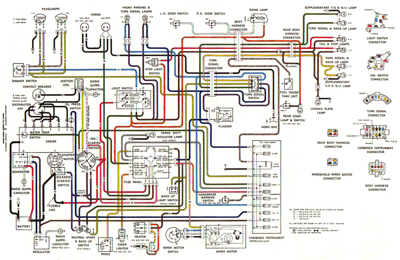
GTR Wiring Harness
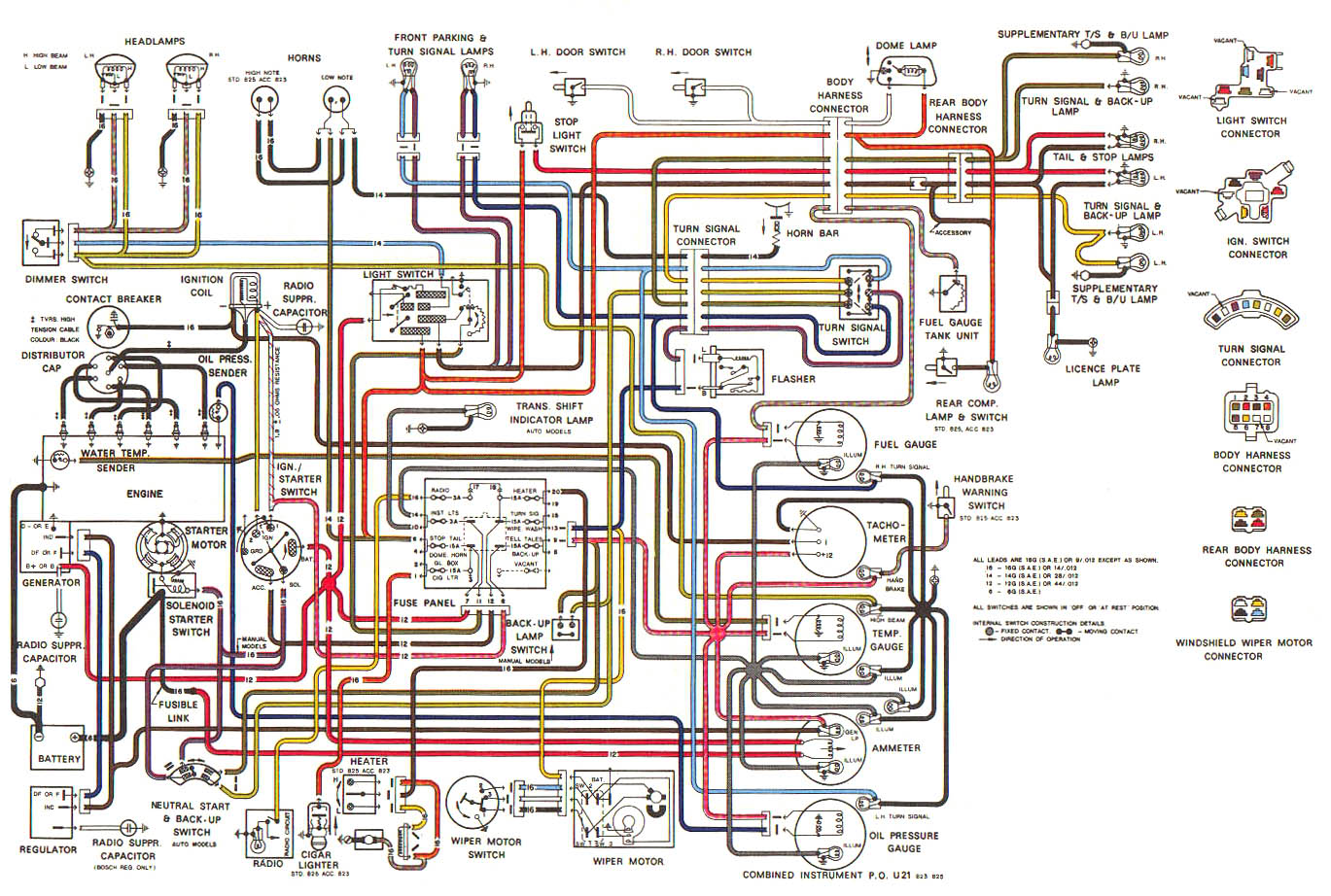
Cheers
Les
Standard Wiring Harness
GTR Wiring Harness
Cheers
Les
#14
_jtfenech_
_jtfenech_
-
- Guests
Posted 23 November 2013 - 01:13 PM
anyone know what the yellow wire running from the ignition switch to the coil is for as there is already active coming from the resistive wire cant work out why there are two wire running to the coil
#15
_ljshawn_
_ljshawn_
-
- Guests
Posted 23 November 2013 - 01:37 PM
It is to bypass the resistive wire to give 12 volts to the coil to help with starting
#16
_jtfenech_
_jtfenech_
-
- Guests
Posted 23 November 2013 - 02:59 PM
nice so I don't need it then cause iv got electronic ignition
#17
Dr Terry
-

- Moderators
-
- 3,276 posts
Technical + Numbers Guru + Moderator
- Location:Eastwood (Sydney) NSW
- Joined: 13-November 05
Posted 28 November 2013 - 10:09 AM
Where does your electronic ignition system get its 12V supply from ?
Dr Terry
Dr Terry
#18
_jtfenech_
_jtfenech_
-
- Guests
Posted 28 November 2013 - 05:17 PM
I ran a cable from the ignition barrel to the coil teed into the pink wire on the key barrel same place the resistive wire is joined then I cut away the resistive wire
the previous owner fitted the electronic ignition and left the resistive wire in ran like shit till I fixed it he had no idea iv fixed so many stupid things like that
#19
Dr Terry
-
- Moderators
-
- 3,276 posts
Technical + Numbers Guru + Moderator
- Location:Eastwood (Sydney) NSW
- Joined: 13-November 05
Posted 01 December 2013 - 09:26 AM
You will still need the yellow wire to feed the coil its 12Vsupply during cranking. Your new wire from the ignition switch will not do this.
Dr Terry
#20
S pack
-

- Members
-
- 15,538 posts
Scrivet Counter
- Name:Dave
- Location:Luggage Point
- Car:73 LJ
- Joined: 25-January 10
Posted 01 December 2013 - 10:41 AM
You will still need the yellow wire to feed the coil its 12Vsupply during cranking. Your new wire from the ignition switch will not do this.
Dr Terry
I believe from reading what jtfenech has posted he hasn't disconnected the yellow wire, just bypassed and disconnected the pink wire.
#21
_jtfenech_
_jtfenech_
-
- Guests
Posted 01 December 2013 - 07:53 PM
sounds like I may have cocked up I'm still running wiring and have no battery so I haven't tested yet but iv completely removed the yellow wire from the circuit
ill find out soon if its an issue I guess, easy enough to fix if it an issue though just trying to eliminate as much wireing as possible
#22
S pack
-
- Members
-
- 15,538 posts
Scrivet Counter
- Name:Dave
- Location:Luggage Point
- Car:73 LJ
- Joined: 25-January 10
Posted 01 December 2013 - 08:03 PM
sounds like I may have cocked up I'm still running wiring and have no battery so I haven't tested yet but iv completely removed the yellow wire from the circuit
ill find out soon if its an issue I guess, easy enough to fix if it an issue though just trying to eliminate as much wireing as possible
Mate you need the yellow wire to the coil + connection. Just bridge the pink resistance wire connector to the yellow wire at the ignition switch wiring connector.
Apologies Dr Terry, you read that one correctly.
Cheers
Dave.


0 user(s) are reading this topic
0 members, 0 guests, 0 anonymous users

