Jump to content


Delco HEI into Holden 6 How-To


  • Please log in to reply
81 replies to this topic

#26 _oldjohnno_

_oldjohnno_
  • Guests

Posted 09 March 2011 - 08:58 AM

One thing i noticed was that i could fit the cap in 2 different positions on the unit i got. I only realized this after i refitted the cap & noticed that 2 of the cap retaining arms were not seated correctly (as viewed from underneath) but 2 were. I presume that this would affect the phasing of the rotor to cap. I didnt actually try it in the other position when in the car but may try one day to see the result. Just thought i would mention it.


Good point and something to keep in mind. I'm pretty sure this cap was properly positioned but I'll check it to be sure - I've done dumber things in the past after all..

#27 _oldjohnno_

_oldjohnno_
  • Guests

Posted 06 October 2011 - 07:47 PM

Did another one of these the other day and came across something worth mentioning. I'd removed the standard module to replace it with a Davis unit, and when I did I found that one of the tapped holes that retain the module had a big burr on it. The burr held one end of the module clear of the plate and there was only the thinnest film of heat paste on the back. So as a result there was basically no contact between the module and plate, and because of this I wouldn't have expected the original module to last long.
Just thought I'd mention it in case other dissies are similarly affected. In future I think I'll check them before installation - it only takes a couple of minutes to do and these are after all, $50 - $60 distributors.

#28 Stinga

Stinga

    .

  • Members
  • PipPipPipPipPip
  • 2,114 posts
  • Name:Stinga
  • Location:Wollongong, NSW
  • Car:HD Holden ute, and sedan, UC torana
  • Joined: 05-December 05

Posted 02 December 2011 - 12:14 AM

When anyone else does this, can you take pics at each step of the way and post them up. Then I can add them into the appropriate spot Posted Image

Grant..


Posted Image
Posted Image
Posted Image
Posted Image
Posted Image

#29 _oldjohnno_

_oldjohnno_
  • Guests

Posted 19 February 2012 - 08:49 PM

A bit of further information on these things:

The Chevy 250-292 dissie is basically the same unit apart from the gear, so the conversion process would be the same as well. Which one you choose would come down to price and availability I guess. I don't know what the difference is in advance curves between the two.

The quality control on these is patchy, so I'd certainly completely strip and reassemble them while doing the conversion. Doesn't take long and hey, it's a 60 buck dissy...

The existing curve is usable for a bone-stock engine, but for anything fairly hot you'll have waaaaaaaaaaay too much total (well over 40deg at higher revs). I've had good results from welding up and grinding the slot to limit the amount of movement to about 15 - 18deg (crank) and using the weights and the stiffest springs from the Moroso kit. I used the existing cam plate but trimmed the small tail of the Moroso weights slightly to allow them to fully close. I found the new weights fouled very slightly with a Davis rotor but was fine with the original. Whatever you use it would pay to check it.

As mentioned previously the cap can fit in two positions, only one of which will work properly. There is a locating lug on the cap but for some reason two notches in the body. Rule of thumb is to always fit the cap so the connector is directly above the vac advance unit.

#30 Stinga

Stinga

    .

  • Members
  • PipPipPipPipPip
  • 2,114 posts
  • Name:Stinga
  • Location:Wollongong, NSW
  • Car:HD Holden ute, and sedan, UC torana
  • Joined: 05-December 05

Posted 19 February 2012 - 09:17 PM

does the davis cap fit the cheap dizzy? maybe some pics of welding the slot to limit the advance would be useful for the thread( and me!)

#31 _oldjohnno_

_oldjohnno_
  • Guests

Posted 19 February 2012 - 09:37 PM

The Davis cap, coil and module all fit fine. The rotor only barely fouled in one spot but it was enough that you could feel it when you turned the rotor back and forth against the springs. It'd take less than 10 seconds with a Dremel to fix it but being basically lazy I just used the old rotor.
Next one I do I'll take some photos as I go.

#32 _barbermi_

_barbermi_
  • Guests

Posted 23 February 2012 - 07:40 AM

Hi Guys,

I am looking at this setup for my injected 186.
Is there a way to use this setup as my trigger for a Microtech LT10s?

Cheers.

#33 _oldjohnno_

_oldjohnno_
  • Guests

Posted 23 February 2012 - 08:38 AM

LT10 or LT8?

I wouldn't use a HEI dissy as a trigger, but then I wouldn't be using any dissy at all. It makes no sense to have an ECU capable of driving a direct multi-coil setup and still using a dissy. For any half-serious Holden six that was going to be turning a few revs I'd jump at the chance to dump the damn dissie and all the torsional-vibration related problems that go with it.
Three double ended coils and a crank trigger (ideally at the flywheel end) would be much, much nicer.

#34 _barbermi_

_barbermi_
  • Guests

Posted 25 March 2012 - 12:34 AM

I just finished this conversion also. Very easy to do that is for sure! Great info and thanks!
I have converted the electronic ignition module in the dizzy to drive the ECU.

I do see your point Johnno, but the ease of setting up this dizzy was too hard to pass. It literally took me one beer in the shed and it was done!
Will be an improvement over the stock dizzy and was relatively cheap. I can upgrade to coil packs later if i wish.

cheers

#35 Stinga

Stinga

    .

  • Members
  • PipPipPipPipPip
  • 2,114 posts
  • Name:Stinga
  • Location:Wollongong, NSW
  • Car:HD Holden ute, and sedan, UC torana
  • Joined: 05-December 05

Posted 25 March 2012 - 06:06 PM

As mentioned previously the cap can fit in two positions, only one of which will work properly. There is a locating lug on the cap but for some reason two notches in the body. Rule of thumb is to always fit the cap so the connector is directly above the vac advance unit.


so the pics in the original post have the cap incorrectly fitted?

silly question time, which post do you use for cyl#1, does it matter?

#36 originalglenn

originalglenn

    Forum Fixture

  • Members
  • PipPipPipPipPip
  • 594 posts
  • Location:near bega nsw
  • Joined: 07-November 05

Posted 25 March 2012 - 08:08 PM

doesnt matter but i used the one that was facing number 1

edit

as long as you set your dizzy right (look it up) you can choose any of the posts as number 1

Edited by originalglenn, 25 March 2012 - 08:18 PM.


#37 _oldjohnno_

_oldjohnno_
  • Guests

Posted 25 March 2012 - 08:40 PM

so the pics in the original post have the cap incorrectly fitted?

silly question time, which post do you use for cyl#1, does it matter?


Thats right, the pics in the first post show the cap fitted wrongly. The two notches in the body are a real trap. They're 90 deg apart so while it wouldn't make any difference with a V8 with a six it certainly does.

As OG says it doesn't matter where No 1 is but most people make the forwardmost terminal No 1 simply because it's easy to remember, plus it keeps the wiring fairly tidy.

#38 Stinga

Stinga

    .

  • Members
  • PipPipPipPipPip
  • 2,114 posts
  • Name:Stinga
  • Location:Wollongong, NSW
  • Car:HD Holden ute, and sedan, UC torana
  • Joined: 05-December 05

Posted 25 March 2012 - 09:08 PM

i found i had the cap in the wrong spot today, it was right when i first fitted it to the car but i took it off when i changed the leads. i had not noticed until today as it started and idled fine, just when i went to drive it down the road it coughed and farted. i think i will mark the cap and body with a texta to avoid future brain farts.

#39 _Bomber Watson_

_Bomber Watson_
  • Guests

Posted 25 March 2012 - 10:00 PM

And this man works on helicopters :tease:

Cheers.

#40 Stinga

Stinga

    .

  • Members
  • PipPipPipPipPip
  • 2,114 posts
  • Name:Stinga
  • Location:Wollongong, NSW
  • Car:HD Holden ute, and sedan, UC torana
  • Joined: 05-December 05

Posted 25 March 2012 - 10:05 PM

And this man works on helicopters :tease:

Cheers.


when im sober..

#41 _Bomber Watson_

_Bomber Watson_
  • Guests

Posted 25 March 2012 - 10:11 PM

ish

#42 _oldjohnno_

_oldjohnno_
  • Guests

Posted 26 March 2012 - 06:14 AM

And this man works on helicopters :tease:

Cheers.


You can be as sloppy as you like with helicopters - if something goes badly wrong the crew is returned to the ground automatically.

#43 _oldjohnno_

_oldjohnno_
  • Guests

Posted 06 April 2012 - 08:49 AM

Something else that might be worth mentioning: nearly all magnetically triggered ignitions (including HEIs) will have some amount of built in retard with increasing rpms. It's generally not an issue with stock or mild engines because the advance mechanism doesn't usually bottom out and the rpms aren't high enough to cause much retard anyway.

Where it can be a problem is where you have physically limited the movement of the advance mechanism and are running higher rpms. For example, lets say you have limited the centrifugal to 15deg (crank) all in by say 3500. You hook up the timing light and rev the engine to where the advance finishes (3500) and set the total to 30degrees. The trouble with this is that because of lag in the magnetic trigger there is a built in retard of around 1 to 1.5degrees per 1000rpm. So by the time you get to 7500 you may only have 25 degrees total instead of the 30 you thought you had. Bottom line is you need to account for this when setting up the advance mechanism and/or the initial.

But as I mentioned earlier, you don't normally need to worry with stock or mildish builds, and it's something that affects pretty much all mag-triggered ignitions, not just HEIs.

#44 _oldjohnno_

_oldjohnno_
  • Guests

Posted 06 April 2012 - 04:15 PM

maybe some pics of welding the slot to limit the advance would be useful for the thread( and me!)


Here's a pic of one with the slot welded and ground to limit the total advance. You can use a drill bit as shown in the pic as a gauge to measure how much movement is left. Depending on how much total and initial you need this'll vary but usually 9/64" to 5/32" will be close. It's only necessary to weld one slot; the notch ground alongside it is just to keep it roughly in balance.
I just welded a small section of 5/16" bolt into the slot and ground it out. If desired you could also weld the other end of the slot if you wanted to put a bit more preload on the springs to slightly delay the start of advance.

Posted Image

#45 aus_yzman

aus_yzman

    Forum Participant

  • Members
  • PipPip
  • 6 posts
  • Name:Mika
  • Location:Brisbane
  • Car:LC torana 4 door
  • Joined: 29-January 12
Garage View Garage

Posted 28 November 2012 - 05:19 PM

Another way to limit your mech advance is to use a screw and file the side down as per this photo

Attached File  HEIadvlimitlock2.jpg   72.39K   14 downloads

#46 _glennhailstone_

_glennhailstone_
  • Guests

Posted 23 May 2014 - 02:07 PM

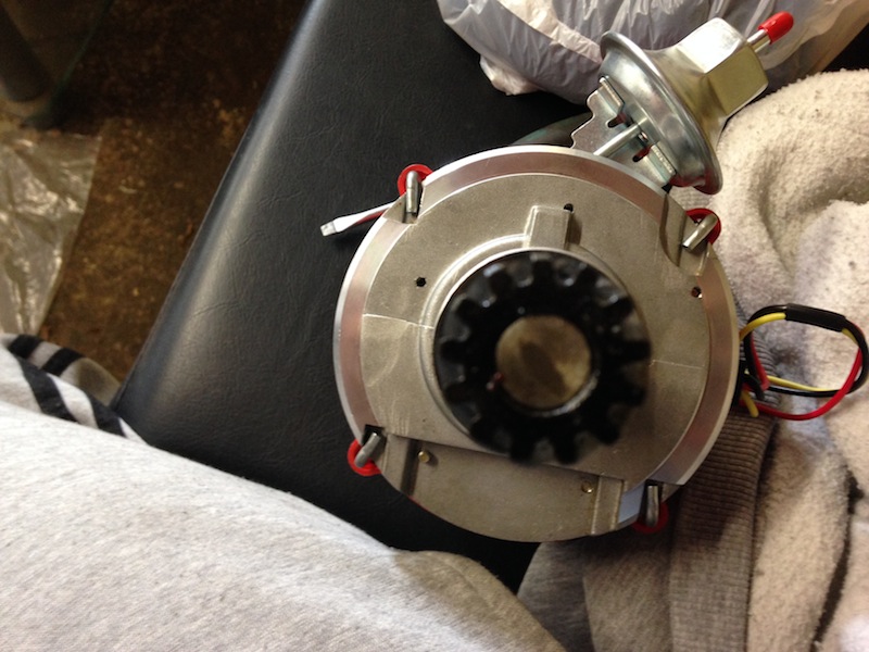
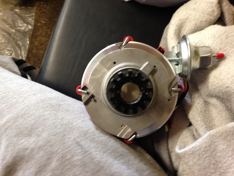
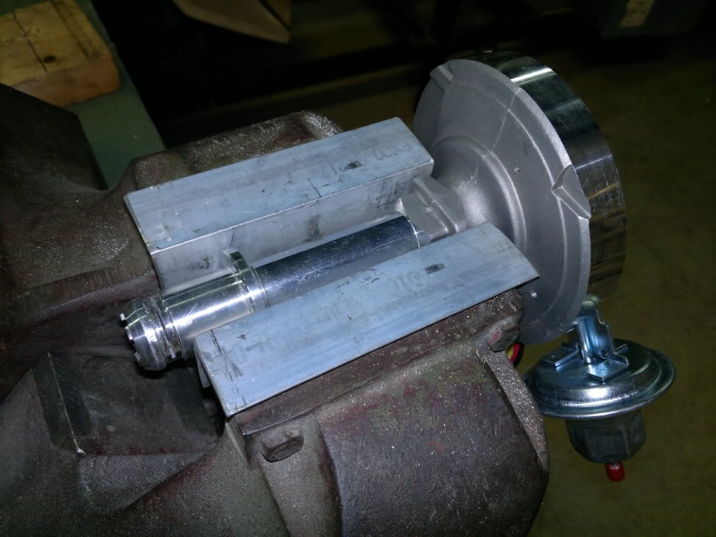
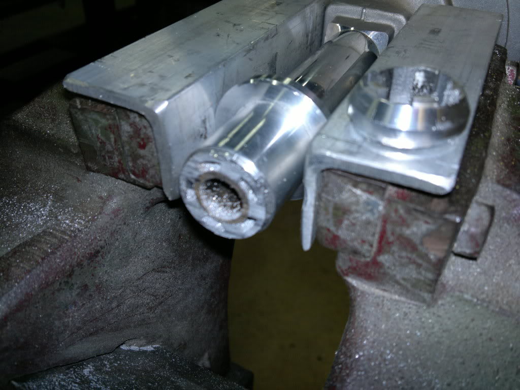
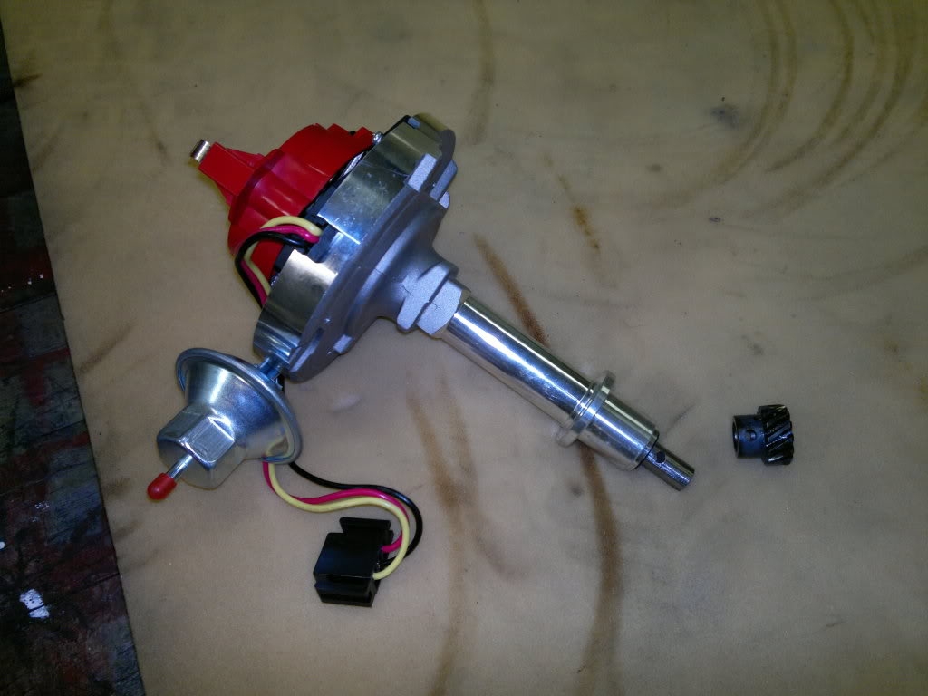
Hi all, I bought this one from ebay, it looks like the one being talked about here, its going on my worked newly built 186. Does anybody know how much has been done to it, like know the guy who sells them.


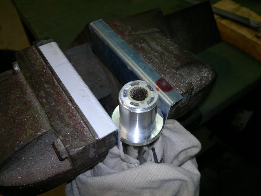
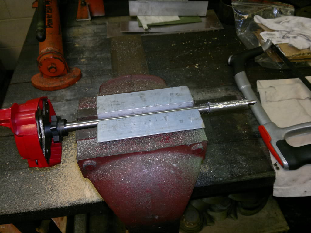
Also can I get more information on this "The existing curve is usable for a bone-stock engine, but for anything fairly hot you'll have waaaaaaaaaaay too much total (well over 40deg at higher revs). I've had good results from welding up and grinding the slot to limit the amount of movement to about 15 - 18deg (crank) and using the weights and the stiffest springs from the Moroso kit. I used the existing cam plate but trimmed the small tail of the Moroso weights slightly to allow them to fully close. I found the new weights fouled very slightly with a Davis rotor but was fine with the original. Whatever you use it would pay to check it.

I dont know much about dizzy's so if somebody could dumb it down a bit for me that would be great.


Another thing is I am trying to set up my newly rebuilt engine and I can do the mechanical stuff alright, but I have no idea how to set up the dizzy. So which order do I put the HE leads on, and how do you know which way to rotate the dizzy. I dont know any of this so some easy to understand instructions would be nice.


Thanks heaps


dizzy_zpsee25cde1.jpg


Edited by glennhailstone, 23 May 2014 - 02:10 PM.


#47 _glennhailstone_

_glennhailstone_
  • Guests

Posted 15 July 2014 - 06:10 AM

Im setting one of these up now. You can get these already converted for a Red 6 on ebay. However I did have to change the drive gear because the gear that was on there was going the opposite way. Still pretty good.


Can somebody please let me know how to set these up in regards to power. Theres two wires coming out of the original wiring loom (LC Torana) which seem to head towards the dissy, but I don't know what they are.

They could be A. 12V B. oil pressure gauge or C. Tacho. Sorry but I have no idea, any help here would be great.


It is recommended that you use a 12V relay because they need constant 12V.


Also if your not using the vac advance, (because webers don't have vac advance) can you just leave the plastic cap on or do you have to remove the whole thing.


Cheers


#48 _glennhailstone_

_glennhailstone_
  • Guests

Posted 04 September 2014 - 06:27 PM

Just trying to fire up the old girl for the first time with this delco dissy. And Im finding theres no spark at the plug.


I have tried to narrow down the problem, so I put a multimeter on the coil, (the little round metal part that pushes the spring which goes to the rotor and there is no voltage there with the ignition on. But there is 12Vs at the red and yellow wires that go to the coil. This is a brand new dissy, so I don't know. I have followed all your other instructions, so now Im scratching my head.


Cheers


#49 _glennhailstone_

_glennhailstone_
  • Guests

Posted 05 September 2014 - 06:09 AM

Well at the moment I can tell you first hand that these dissy's are cheap and nasty and not worth the hassle of modifying. Still persevering. 


#50 _glennhailstone_

_glennhailstone_
  • Guests

Posted 05 September 2014 - 08:04 AM

"As mentioned previously the cap can fit in two positions, only one of which will work properly. There is a locating lug on the cap but for some reason two notches in the body. Rule of thumb is to always fit the cap so the connector is directly above the vac advance unit."


I have tried to turn the cap as stated above, however when I do this the rotor does not line up with the cap terminals, and the hold down clamps do not line up properly. See photos.


dis1_zps0656ac1c.jpgdis2_zpsc276e324.jpg


1 user(s) are reading this topic

0 members, 1 guests, 0 anonymous users