
Heh thats a neat trick. What are some causes for flexigauge being inaccurate? When I did it on the mains it was spot on when compared to my Mikes.
My engine build, please look over my shoulder [4 Banger]
Started by
_Viper_
, Dec 03 2011 11:00 PM
66 replies to this topic
#52
 _Ned Loh_
_Ned Loh_
-

- Guests
Posted 21 December 2011 - 01:03 PM
Heh thats a neat trick. What are some causes for flexigauge being inaccurate? When I did it on the mains it was spot on when compared to my Mikes.
I can't answer that question, but I think this is interesting:
"After we torqued the rod cap and then removed it, we used the Plastigage package to compare its width to a particular clearance. While our careful mic measurements indicated a clearance of 0.0031 inch, the Plastigage indicated a much tighter 0.0015-inch clearance-or roughly half of what we mic'd. We double-checked our measurements, but the results were within 0.0001 inch."
Read more: http://www.carcraft....l#ixzz1h8OgFCxn
Edited by Ned Loh, 21 December 2011 - 01:04 PM.
#53
_oldjohnno_
_oldjohnno_
-
- Guests
Posted 21 December 2011 - 08:03 PM
I've never come across anything like that before, weird. One nice thing about plastigage is that it can sometimes show things that don't show up with mikes. Eg. if you have a rod or a shaft with a slight bend the bearing clearance will mike up perfectly but when you check it with plastigage it will be tapered along its length, showing that the bearing is cockeyed.
#54
_oldjohnno_
_oldjohnno_
-
- Guests
Posted 21 December 2011 - 10:27 PM
Just thinking about how plastigage can show up stuff you wouldn't otherwise find and the CarCraft problem - there's one possibility I can think of:
Not every shape with a constant diameter is a circle. Think of a shape similar to a Wankel rotor (but not nearly as pronounced of course) - you could check it for ovality with mikes for as long as you liked and it would come up looking fine. You could get the same thing with other shapes having an odd number of nodes. But depending on where the plastigage was placed on the journal it would either show the same as the miked clearance or possibly much less, even zero. But you wouldn't pick up the actual journal shape unless you clocked the shaft between centres or on vee blocks.
Not every shape with a constant diameter is a circle. Think of a shape similar to a Wankel rotor (but not nearly as pronounced of course) - you could check it for ovality with mikes for as long as you liked and it would come up looking fine. You could get the same thing with other shapes having an odd number of nodes. But depending on where the plastigage was placed on the journal it would either show the same as the miked clearance or possibly much less, even zero. But you wouldn't pick up the actual journal shape unless you clocked the shaft between centres or on vee blocks.
#55
TerrA LX
-

- Members
-

- 14,241 posts
Fulcrum Fixture
- Location:Sid 'n' knee
- Joined: 31-May 06
Posted 22 December 2011 - 10:51 AM
I had one of the rods fitted with bearings and Torqued down and he measured with his Internal Mike (I didnt have one small enough) and with his measurement he came up with 2.4thou clearance between the Rod and Crank... hmm so hopefully he didn't just make up a measurement right in front of me (I couldnt get a good look at the mike, Thinking now I shoulda asked to do it myself)
2.4thou would be ok, but why did I only get 1.5 thou reading with the flexigauge...
I read this several times but I am not quite sure how he got 2.4thou.
Did he mike the crank journal and then internal mike the torqued rod with bearing subtracting the second measurement from the first in front of you?
#56
_Viper_
_Viper_
-
- Guests
Posted 22 December 2011 - 03:09 PM
I miked the crank myself, used a standard first and triple checked so hopefully accurate, then I fitted a bearing to a rod and torqued It up and took it down to him and he internally miked it and subtracted my measurement from the rods measurement.
Edited by Viper, 22 December 2011 - 03:10 PM.
#57
TerrA LX
-
- Members
-
- 14,241 posts
Fulcrum Fixture
- Location:Sid 'n' knee
- Joined: 31-May 06
Posted 22 December 2011 - 03:14 PM
So someone's mike might be out a bit?
Might account for the discrepancy.
Might account for the discrepancy.
#58
_Viper_
_Viper_
-
- Guests
Posted 22 December 2011 - 09:03 PM
I checked mine with a 1" and 2" standard and was spot on (was a 1" to 2" mike) So mine should be right.. and Id hope he keeps his in check.
But yes using 2 different mikes could cause slight differences. I did have a play with my telescopic snap internal mikes (or whatever there called) Then measured that with my micrometer And I worked it out to be 2thou (could repeat the same measurement a few times and got the same)
Like these

But yes using 2 different mikes could cause slight differences. I did have a play with my telescopic snap internal mikes (or whatever there called) Then measured that with my micrometer And I worked it out to be 2thou (could repeat the same measurement a few times and got the same)
Like these
#59
TerrA LX
-
- Members
-
- 14,241 posts
Fulcrum Fixture
- Location:Sid 'n' knee
- Joined: 31-May 06
Posted 23 December 2011 - 08:03 AM
I used to work to tolerances of 0.25mm and I can tell you it is not easy to measure accurately.
A bit of wear here and a little error there and the tolerance is gone.
A bit of wear here and a little error there and the tolerance is gone.
#60
_Viper_
_Viper_
-
- Guests
Posted 26 December 2011 - 12:52 AM
Firstly I apologize for the next section, I didn't check the pics I took till after I had finished fitting all the pistons and realized I didn't get all the pics I should have. So i'll do the best with what I have.
Fitting Pistons & Rods
First secure the piston/rod into a Vice, Some alloy angle iron or some rags will stop the Vice from marring the Rod

The first rings to go on are the Oil control rings which go into the bottom slot (Ring land) In order from left to right is Bottom oil ring, Oil Expander ring, Top oil ring (ps. Top and bottom oil rings are identical)

There is 2 ways to fit rings, Oil rings are alot more flexible so I'll show you the basic way first, Altho abit hard with just pics, I should have take a video.
Stick one end of the ring into the groove and then sort or Spiral it into place. Be careful at the end to make sure the other end of the ring doesnt scratch the side of the piston as you put it into place.

I found out after fitting that first oil ring that I needed to fit the expander ring first and then the top and bottom oil rings. (Not all ring packs are like this so just check when you do yours)

I failed to get a pic of all the oil rings fitted. But basically the expander goes in the middle with a oil ring on top and below it.
Next grab the compression rings that we file fitted earlier and organized into the respective bore

The other way to fit rings is with a Ring expander tool, which is fairly cheap and what Id recommend for the compression rings as they are alot stiffer then the oil rings. Altho it is very do-able without one using the previous method.

Fit the 2nd ring first, making sure you face it up the right way (there will be a marking showing the top) And then fit the 1st/top ring.
All done

Next we have to arrange the ring gaps... as you fit the rings it helps to put the rings in the orientation that they need to be, but either way check the instructions that came with the rings or your workshop manual and you should find something like this

So you basically just spin the rings so that the gaps (openings) are facing the direction shown.
Remove the piston from the Vice and flip it over. Clean the bearing surface of the rod.

Remember to check the bearing is the correct size and its also clean then fit to the rod.

Didn't get a pic, but put a smear of oil or assembly lube onto the bearing and the sides of the rod (where it will be touching the crank)
Spin the crank so that the journal your about to fit the piston/rod to is at bottom dead center like so.

Also put a smear of assembly lube on the crank where the rod will sit.
Next we are going to slot the piston/rod down into the bore. My rods are different to normal as they have separate bolts... usually the bolts are permanently fitted to the rods and you need to cover them to protect the bores and crank from damage while you slide it in. I short length of fuel hose slipped over the bolts does the trick or you can get little covers like these (pic from when I built Dans motor)
Ok I also failed to get pics of the next step but first make sure the bores are spotless by wiping them out with a clean rag, Then pour a little bit of oil onto your fingers and coat the bore walls. Then do the same with the pistons covering the rings and the skirts.
Now slip the piston into the bore, careful not to let the rod scrape against the sides. I like to put something through the pin to hold it up off the deck a little like so, Double check all your ring gaps are in the correct orientation at this stage also.

This makes it easy to fit the ring compressor tool and cover all the rings. I bought this one from summit racing but you can get ones from supercheap, repco etc, just make sure its a nice snug fit.

Lift the piston a touch and remove whatever you used to stick through the pin, then lower it back down and give the compressor soft taps around the edge to make sure its all even and flat against the deck.
Then while putting pressure on the ring compressor give the top of the piston some firm taps pushing it down into the bore. Be resonably gentle and if you give the piston a tap and it doesnt move there is a good chance one of the rings has popped out of the expander... Dont keep hitting the piston or you can snap the ring. You will have to pull the piston out of the bore abit again and start again.

Once all the rings are past the top of the deck the piston ring compressor will come loose... Keep tapping the piston down the bore but keep an eye on the bottom and be sure to guide the rod over the crank.

Once its fully seated on the crank spin the motor over. (dont worry about the piston falling out, the rings will hold it in place)

Now we want to repeat the same process as we did with the crank and flexibleguage to check the clearance with a couple differences.
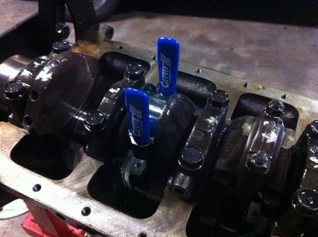
First we need to stop the crank from spinning, use whatever method you see fit, but this was how I did it.

Remember to clean and fit the bearing to the rod cap, no goo for the moment while using the flexigauge. Apply the relavent lube to the rod bolts and Torque down the rod cap to spec. Undo the bolts and remove the cap (might need some upward taps with a hammer) and check your clearance.

I got about 1.5-1.7 thou on each of mine, I would have preferred it to be closer to 2.5 thou but it is within limits. if its below 1 or above 3 then there is a problem and you will have to consult your machine shop.
Then you can clean off the left over plastigauge, lube the crank and bearing and fit the Rod cap, Torque the rod bolts to spec. Its preferred to use a Rod bolt stretch gauge... And I did buy one, But for the life of me could not get repeatable results. will have to see someone about that.
Each time you finish fitting one piston/rod spin the crank 360 degrees and it should feel smooth the whole time and for a couple degrees at TDC and BDC will be very easy to spin as the piston doesn't move. But if it feels overly tight or gets stuck at a point something is wrong. you should be able to spin the crank by pushing on the counterweights by hand. each piston you fit will make it slightly harder to spin due to the increased drag of the rings.
Also give the bores a visual inspection and make sure there is no new gouges/scratches which would mean one of the rings was damaged during install or there was a burr on the ring or piston.
So that's your Rotating assembly all fitted.

Fitting Pistons & Rods
First secure the piston/rod into a Vice, Some alloy angle iron or some rags will stop the Vice from marring the Rod
The first rings to go on are the Oil control rings which go into the bottom slot (Ring land) In order from left to right is Bottom oil ring, Oil Expander ring, Top oil ring (ps. Top and bottom oil rings are identical)
There is 2 ways to fit rings, Oil rings are alot more flexible so I'll show you the basic way first, Altho abit hard with just pics, I should have take a video.
Stick one end of the ring into the groove and then sort or Spiral it into place. Be careful at the end to make sure the other end of the ring doesnt scratch the side of the piston as you put it into place.
I found out after fitting that first oil ring that I needed to fit the expander ring first and then the top and bottom oil rings. (Not all ring packs are like this so just check when you do yours)
I failed to get a pic of all the oil rings fitted. But basically the expander goes in the middle with a oil ring on top and below it.
Next grab the compression rings that we file fitted earlier and organized into the respective bore
The other way to fit rings is with a Ring expander tool, which is fairly cheap and what Id recommend for the compression rings as they are alot stiffer then the oil rings. Altho it is very do-able without one using the previous method.
Fit the 2nd ring first, making sure you face it up the right way (there will be a marking showing the top) And then fit the 1st/top ring.
All done
Next we have to arrange the ring gaps... as you fit the rings it helps to put the rings in the orientation that they need to be, but either way check the instructions that came with the rings or your workshop manual and you should find something like this
So you basically just spin the rings so that the gaps (openings) are facing the direction shown.
Remove the piston from the Vice and flip it over. Clean the bearing surface of the rod.
Remember to check the bearing is the correct size and its also clean then fit to the rod.
Didn't get a pic, but put a smear of oil or assembly lube onto the bearing and the sides of the rod (where it will be touching the crank)
Spin the crank so that the journal your about to fit the piston/rod to is at bottom dead center like so.
Also put a smear of assembly lube on the crank where the rod will sit.
Next we are going to slot the piston/rod down into the bore. My rods are different to normal as they have separate bolts... usually the bolts are permanently fitted to the rods and you need to cover them to protect the bores and crank from damage while you slide it in. I short length of fuel hose slipped over the bolts does the trick or you can get little covers like these (pic from when I built Dans motor)
Ok I also failed to get pics of the next step but first make sure the bores are spotless by wiping them out with a clean rag, Then pour a little bit of oil onto your fingers and coat the bore walls. Then do the same with the pistons covering the rings and the skirts.
Now slip the piston into the bore, careful not to let the rod scrape against the sides. I like to put something through the pin to hold it up off the deck a little like so, Double check all your ring gaps are in the correct orientation at this stage also.
This makes it easy to fit the ring compressor tool and cover all the rings. I bought this one from summit racing but you can get ones from supercheap, repco etc, just make sure its a nice snug fit.
Lift the piston a touch and remove whatever you used to stick through the pin, then lower it back down and give the compressor soft taps around the edge to make sure its all even and flat against the deck.
Then while putting pressure on the ring compressor give the top of the piston some firm taps pushing it down into the bore. Be resonably gentle and if you give the piston a tap and it doesnt move there is a good chance one of the rings has popped out of the expander... Dont keep hitting the piston or you can snap the ring. You will have to pull the piston out of the bore abit again and start again.
Once all the rings are past the top of the deck the piston ring compressor will come loose... Keep tapping the piston down the bore but keep an eye on the bottom and be sure to guide the rod over the crank.
Once its fully seated on the crank spin the motor over. (dont worry about the piston falling out, the rings will hold it in place)
Now we want to repeat the same process as we did with the crank and flexibleguage to check the clearance with a couple differences.
First we need to stop the crank from spinning, use whatever method you see fit, but this was how I did it.
Remember to clean and fit the bearing to the rod cap, no goo for the moment while using the flexigauge. Apply the relavent lube to the rod bolts and Torque down the rod cap to spec. Undo the bolts and remove the cap (might need some upward taps with a hammer) and check your clearance.
I got about 1.5-1.7 thou on each of mine, I would have preferred it to be closer to 2.5 thou but it is within limits. if its below 1 or above 3 then there is a problem and you will have to consult your machine shop.
Then you can clean off the left over plastigauge, lube the crank and bearing and fit the Rod cap, Torque the rod bolts to spec. Its preferred to use a Rod bolt stretch gauge... And I did buy one, But for the life of me could not get repeatable results. will have to see someone about that.
Each time you finish fitting one piston/rod spin the crank 360 degrees and it should feel smooth the whole time and for a couple degrees at TDC and BDC will be very easy to spin as the piston doesn't move. But if it feels overly tight or gets stuck at a point something is wrong. you should be able to spin the crank by pushing on the counterweights by hand. each piston you fit will make it slightly harder to spin due to the increased drag of the rings.
Also give the bores a visual inspection and make sure there is no new gouges/scratches which would mean one of the rings was damaged during install or there was a burr on the ring or piston.
So that's your Rotating assembly all fitted.
#61
_Viper_
_Viper_
-
- Guests
Posted 30 December 2011 - 05:27 PM
Ok well I was a little worried about the big end clearance still, So I removed one of the rods/pistons... Re torqued the cap onto the rod out of the block and took the block and rod down to A1 High Performance for Leon to check for me. His measurement was 2 thou clearance. so I was trying to figure out why my flexigauge was so far out then I realized I had put assembly lube on the rods as I fit them to the block, so there was a layer of lube between the rod and crank, I left the rod cap and other side of the crank dry. so im thinking the lube was taking up the extra clearance?
#62
_oldjohnno_
_oldjohnno_
-
- Guests
Posted 30 December 2011 - 06:00 PM
One way to find out, try it again dry and see what you get. Why would you oil it if the cap had to come off again anyway?
Things look different in a photo to in the flesh I know, but in the second last photo in the post above the plastigage looks to be a closer match to 2 thou than 1.5thou.
Things look different in a photo to in the flesh I know, but in the second last photo in the post above the plastigage looks to be a closer match to 2 thou than 1.5thou.
#63
_Viper_
_Viper_
-
- Guests
Posted 30 December 2011 - 06:59 PM
I see what you mean about the pic, But when I was checking the flexigauge was deffinately wider then the 2thou scale, it was just a tiny bit smaller then the 1.5.
And I lubed the rod side because I for whatever reason didnt think about it effecting the reading and then all I had to do is remove the cap and lube the cap side and replace cap. Live and learn.
And I lubed the rod side because I for whatever reason didnt think about it effecting the reading and then all I had to do is remove the cap and lube the cap side and replace cap. Live and learn.
#64
_Ned Loh_
_Ned Loh_
-
- Guests
Posted 20 January 2012 - 01:41 PM
Next time I'd suggeat you do a mock assembly part way through the machining process. Needs to be done anyway to work out how much to take off the deck etc. That way you can check main and big end clearances and if they are out you can discuss with machnist when you drop back to them for final machine work.
#65
_AD_75_
_AD_75_
-
- Guests
Posted 20 January 2012 - 03:42 PM
Thanks for puttin up this thread viper, it was a good refresher and an interesting read! Im assuming you will..but are you going to be including assembly of the cylinder head?
Cheers.
Cheers.
#66
_Viper_
_Viper_
-
- Guests
Posted 20 January 2012 - 07:56 PM
Hey Ned, yea the machine shop did the mock assembly to check deck height etc, next time ill be more hands on.
Thanks AD_75, Yea Ill continue the writeup for the head assembly altho its a OHC head so not everything will relate to cam in block motors.
I was planning to build my custom intake manifold and have it flow tested along with the head, but my head man passed away recently so ill have to find someone else.
#67
_308build_
_308build_
-
- Guests
Posted 10 April 2017 - 09:13 PM
I like your method of checking the ring gap.
i did mine this way but without the ring in the oil groove i figured the piston is reasonably square anyway i used the piston length to measure the gaps at various depth in the bore


0 user(s) are reading this topic
0 members, 0 guests, 0 anonymous users

