
Hi Guys.
When piston number 1 is at the very top (top dead center) on a holden 186 what position should the rotor button be (electronic dizzy). if i am looking at the engine and the 6 spark plugs are facing me that position is 12 o'clock. What hand should the rotor button be?.
Even a pic would be good.
Thanks Daz

Holden Rotor Button Position
Started by
DMLC71
, Apr 18 2012 03:47 PM
24 replies to this topic
#1

DMLC71
-
- Members
-

- 424 posts
Forum Fan
- Name:Daz M
- Location:Melb Vic
- Car:1971 LC 4 door
- Joined: 06-September 09
Posted 18 April 2012 - 03:47 PM
#2
_oldjohnno_
_oldjohnno_
-

- Guests
Posted 18 April 2012 - 05:40 PM
Short answer: it doesn't matter so long as the dissy cap terminal for No. 1 is also in the same position.
Long Answer: Most people make No 1 the forwardmost terminal ie. about 3 o'clock. Its logical and easy to remember and you end up with not so many wires crossing over. So if the rotor button is at 3'oclock with No 1 at TDC on the compression stroke then put the No 1 plug wire into the corresponding spot at 3 o'clock in the dissy cap. Then fit the others in a clockwise pattern following the firing order 153624.
Also beware of the distributor fairies. You can use as many tests as you like to verify that No 1 is indeed on the compression stroke (blow tissue out the plug hole, spin the pushrods with your fingers, lift the rocker cover and visually confirm the valves are closed) but it doesn't guarantee success. By the time you go and grab your timing light the fairies can have your dissy out and refitted exactly 180 degrees out. Crank crank, bang cough fart. It can't possibly be out you think, I triple checked everything. Sure enough, 180 out. I swear I've heard the little bastards laughing at me...
#3
DMLC71
-
- Members
-
- 424 posts
Forum Fan
- Name:Daz M
- Location:Melb Vic
- Car:1971 LC 4 door
- Joined: 06-September 09
Posted 18 April 2012 - 09:05 PM
Thanks old johno for the info.
But to make your answer simple for some one like me. When no1 is TDC and I am droping the dizzy in for the first time, is there a general derection I should put the rotor button as I place the dizzy in or just keep moving it around until it fires.
Thanks Daz
But to make your answer simple for some one like me. When no1 is TDC and I am droping the dizzy in for the first time, is there a general derection I should put the rotor button as I place the dizzy in or just keep moving it around until it fires.
Thanks Daz
#4
_oldjohnno_
_oldjohnno_
-
- Guests
Posted 18 April 2012 - 09:30 PM
OK, first things first. It's not enough just to have No. 1 at TDC, it has to be TDC on the compression stroke. There's lots of ways to check this but probably the easiest is to twist up a tissue and poke it into the No. 1 plug hole. Turn the engine until the marks on the front pulley are just before TDC. If it's on the compression stroke it'll blow out the tissue as it approaches TDC. If it doesn't blow it out turn it one full revolution and stop just before TDC.
Now that you're absolutely sure that No. 1 is near TDC on the compression stroke drop the dissy in so that the rotor is pointing straight ahead ie. at 3 o'clock. You may have to try a few times to get this. Now turn the dissy body until the teeth on the star wheel under the rotor align with the teeth on the piece that surrounds it. Fit the clamp and nip it enough to hold it in position but loose enough that you can still move the dissy by hand.
If the cap has the plug wires attached pull them all off except the centre one. Fit the cap to the dissy. Note which of the terminals on the cap lines up with the rotor button - in other words which one is at 3 o'clock. This is No. 1, so fit a plug wire to this terminal and to No. 1 plug. Move to the next terminal on the cap (clockwise) and wire this one to No. 5. Work your way around the cap connecting each terminal to its plug according to the firing order of 153624. Double check that they are all in the right sequence when you're done.
The engine should now start and you can connect a timing light to check and adjust the timing. Tighten down the dissy bolt and you're all done.
#5
S pack
-

- Members
-
- 15,743 posts
Scrivet Counter
- Name:Dave
- Location:Luggage Point
- Car:73 LJ
- Joined: 25-January 10
Posted 18 April 2012 - 11:47 PM
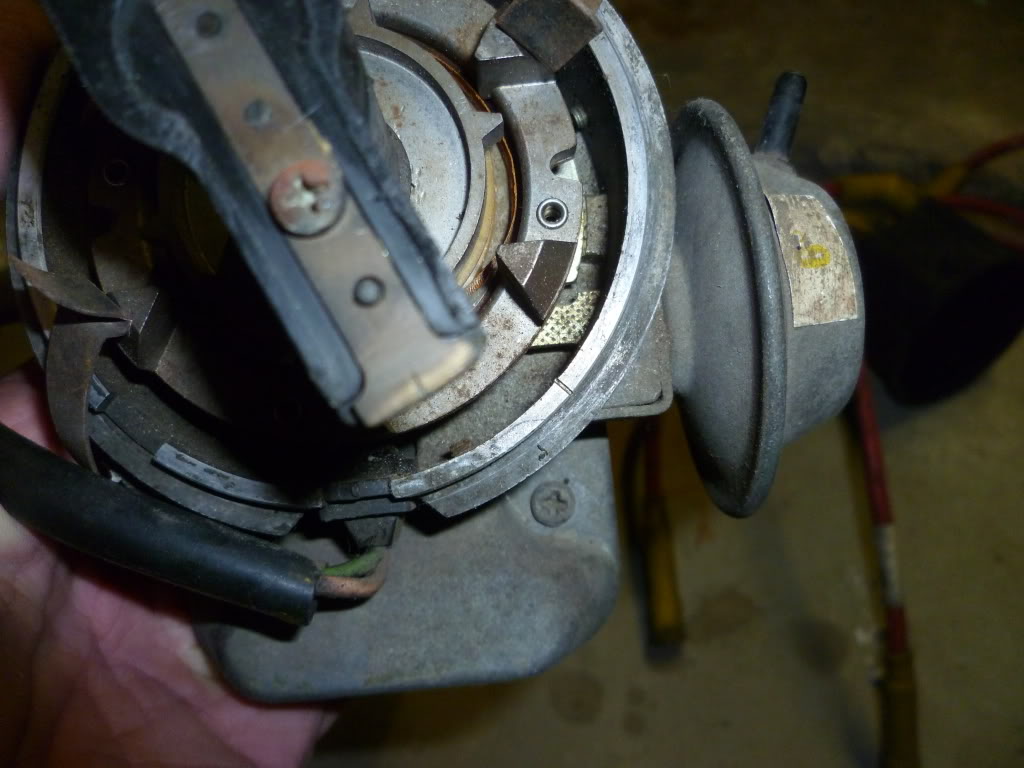
Blue 202 electronic Dizzy. Note the idiot mark Bosch put in the rotor button and dizzy body to denote the No.1 plug lead position.
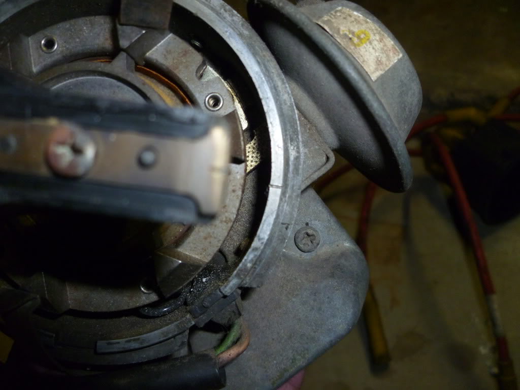
When you install the dizzy you will need to position the rotor past the mark so as the dizzy gear engages the camshaft gear the rotor button will turn back to align with the mark.
Generally the dizzy is installed with the centreline through the vac advance unit parallel to the centreline of the engine.
Edited by S pack, 18 April 2012 - 11:48 PM.
#6
DMLC71
-
- Members
-
- 424 posts
Forum Fan
- Name:Daz M
- Location:Melb Vic
- Car:1971 LC 4 door
- Joined: 06-September 09
Posted 19 April 2012 - 07:55 AM
thanks old Johno and Spack
#7
LX2DR
 View Garage
-

- Members
-
- 1,763 posts
Forum Fixture
- Name:Paul
- Location:Melbourne
- Joined: 21-November 05
View Garage
Posted 19 April 2012 - 08:19 PM
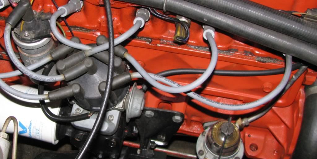
If you set it properly it should be something like this, you can see where No1 is.
Edited by LX2DR, 19 April 2012 - 08:20 PM.
#8
_torbirdie_
_torbirdie_
-
- Guests
Posted 20 April 2012 - 06:46 AM
the pics provided by s pack and lx2dr show exactly how it should be setup. Number one spark lead is more at the 5 oclock position.
This is different to the points dizzy where no.1 is at the 4 oclock position. If you were to have no.1 pointing to 4 oclock on the electronic dizzy, it would be sitting crooked in the car......I know it doesnt affect anything mechanically or electrically......but says to anyone who knows anything about cars that the wally that fitted the dizzy doesnt care for correct detail. There may be also the possibility that a set of plug leads made for the electronic dizzy will only fit akwardly if you dont have it in the 'factory position'
Hadnt really noticed it before, the points dizzy correctly setup has the clips at the 6 oclock and 12 oclock position(with terminals 5 and 2), whereas it is at 8 and 2 oclock on the electronic dizzy. I wonder was it changed as the clips couldnt be put on the module or that someone figured its easier to access the top clip, not get oil on your mitts etc when its not directly facing the block. Or the answer may be that they didnt want the clips directly under the terminals to reduce the chances of shorting for the electronic dizzy cap
Edited by torbirdie, 20 April 2012 - 06:49 AM.
#9
_oldjohnno_
_oldjohnno_
-
- Guests
Posted 20 April 2012 - 01:03 PM
.but says to anyone who knows anything about cars that the wally that fitted the dizzy doesnt care for correct detail...
I guess that makes it official.
I'm a wally.
#10
_Ned Loh_
_Ned Loh_
-
- Guests
Posted 20 April 2012 - 02:28 PM
Off topic...but...in my youth I fitted the dizzy backwards when putting a rebuilt Fraud 1600 Kent engine into a escort. Was a pain in the @rse as the dizzy is under intake manifold. Made nice BIG flames come out of the carby though. 
#11
_oldjohnno_
_oldjohnno_
-
- Guests
Posted 20 April 2012 - 05:31 PM
Off topic...but...in my youth I fitted the dizzy backwards when putting a rebuilt Fraud 1600 Kent engine into a escort. Was a pain in the @rse as the dizzy is under intake manifold. Made nice BIG flames come out of the carby though.
I had a stroke of genius in my youth and dropped a Mini dissy into a VW engine. It was almost a straight swap and I was certain that it was gonna improve things - the VW dissy only had vac advance, no centrifigal. It fired up straight away but when I gave it a rev it was as soggy as a wet sanga.
I'd failed to check the direction of rotation so the centrifugal advance was actually centrifugal retard...
#12
_2ELCS_
_2ELCS_
-
- Guests
Posted 20 April 2012 - 06:34 PM
A pretty clever one IMHOI guess that makes it official.
I'm a wally.
#14
_Bomber Watson_
_Bomber Watson_
-
- Guests
Posted 20 April 2012 - 08:26 PM
What, you get cheques for talking up oldjohnno now??
#15
_oldjohnno_
_oldjohnno_
-
- Guests
Posted 20 April 2012 - 08:38 PM
Thats right Bomber.
Though anyone that'd accept cheques written by me needs their head read...
To be honest I wouldn't be saying anything nice until I had cash in my hand, and I'd taken a good close look at the notes to make sure they're not, um, "aftermarket"...
Though anyone that'd accept cheques written by me needs their head read...
To be honest I wouldn't be saying anything nice until I had cash in my hand, and I'd taken a good close look at the notes to make sure they're not, um, "aftermarket"...
#16
_Bomber Watson_
_Bomber Watson_
-
- Guests
Posted 20 April 2012 - 08:44 PM
Aftermarket shaftermarket they pay little attention at BWS when your handing them over.
#17
_torbirdie_
_torbirdie_
-
- Guests
Posted 21 April 2012 - 05:59 AM
I guess that makes it official.
I'm a wally.
oops.....like to take back that wally remark....
#18
_torbirdie_
_torbirdie_
-
- Guests
Posted 21 April 2012 - 06:23 AM
OK, first things first. It's not enough just to have No. 1 at TDC, it has to be TDC on the compression stroke. There's lots of ways to check this but probably the easiest is to twist up a tissue and poke it into the No. 1 plug hole. Turn the engine until the marks on the front pulley are just before TDC. If it's on the compression stroke it'll blow out the tissue as it approaches TDC. If it doesn't blow it out turn it one full revolution and stop just before TDC.
Be interested to know what method they used on the assembly line: perhaps they made sure of the valve positions before attaching the rocker cover and dizzy installed at that stage?
It would be good to get a list of all the various ways it can be done, not all are convenient for the situation depending on what tools one has or what stage of 'repair' one is at.
Personally, I've only had to do it a couple of times and used proper leak down apparatus to work out whether the valve was closed or not.
One suggestion, I havent tried...would be to remove all the plugs except for number one, which will make it easy to turn by the fan and feel the resistance when arriving at the compression stroke.
Edited by torbirdie, 21 April 2012 - 06:24 AM.
#19
_Ned Loh_
_Ned Loh_
-
- Guests
Posted 21 April 2012 - 08:49 AM
Tools or not, I always use the 'finger in the plug hole' method.
#20
_torbirdie_
_torbirdie_
-
- Guests
Posted 21 April 2012 - 01:20 PM
Tools or not, I always use the 'finger in the plug hole' method.
you can reach from the plug hole to the key switch without a tool/assistant?
Edited by torbirdie, 21 April 2012 - 01:25 PM.
#21
_Moose lc_
_Moose lc_
-
- Guests
Posted 21 April 2012 - 02:01 PM
you can reach from the plug hole to the key switch without a tool/assistant?
I'm going to go with......... No. I'm sure that you could reach the crank with a socket and breaker bar and the plug holes though. TIC
#22
_Ned Loh_
_Ned Loh_
-
- Guests
Posted 21 April 2012 - 02:07 PM
Not sure what you mean? FWIW - I'm talking about finding #1 TDC on compression stroke. Turn it over with a socket and index finger of other hand in plug hole.
#23
LX2DR
View Garage
-
- Members
-
- 1,763 posts
Forum Fixture
- Name:Paul
- Location:Melbourne
- Joined: 21-November 05
View Garage
Posted 21 April 2012 - 02:30 PM
Motor assembler would have left the engine on the firing mark (6o BTDC), then the dissy installer only needs to drop in the dissy with the button pointing in the correct orientation at the idiot mark.
As you put the dissy in, you need to have the button facing around 6 oclock (I think, could be 3 oclock cant remember which way it turns?) when you drop the dissy down and engage the gears the button will rotate to the mark.
If its not perfect, take note of where it is before or after the idiot mark, lift the dissy, move the button in the direction that will put it over the mark.
As you lift and lower the dissy you will get a feel for which way you need to go.
Worst case is 180o out, rotate the crank 1 complete turn back to 6o BTDC, lift the dissy and turn the button 180o and put it back in.
Get out the timing light and set it.
#24
rodomo
-

- Members
-
- 18,051 posts
To advertise here, call 13TORANA
- Name:R - O - B Dammit!
- Location:Way out west of Melbourne Awstraylya
- Joined: 10-December 05
Posted 21 April 2012 - 04:18 PM
You can see No.1 inlet valve by taking the oil cap off on a Holden 6 and, I believe, early 8's?
It is the one forward of the oil cap hole, adjacent to No. 1 inlet runner.
Turn the motor in the direction of rotation.
Watch for this valve to open then close.
Still in direction of rotation, the next time the timing marks line up it is No.1 firing.
If you dont have the harmonic balancer fitted, the crankshaft key should be at 12 O'clock.
#25
orangeLJ
-

- Members
-
- 10,261 posts
Yes, yes I do post alot!
- Joined: 02-May 06
Posted 21 April 2012 - 06:17 PM
Finger inthe plug hole works for me too.
Just ma,e sure when you drop the dizzy in, you give yourself enough room to rotate it for advance/retarding the timing. More important with elec ignition as the module whacks the block.
Just ma,e sure when you drop the dizzy in, you give yourself enough room to rotate it for advance/retarding the timing. More important with elec ignition as the module whacks the block.


0 user(s) are reading this topic
0 members, 0 guests, 0 anonymous users

