Jump to content


LH / LX Electronic instrument cluster conversion


  • Please log in to reply
106 replies to this topic

#1 _434LX_

_434LX_
  • Guests

Posted 06 November 2014 - 10:25 PM

This is a guide of how I converted my LX instrument cluster to late model electronic gauges from start to finish.


The original inspiration for this project came from Andy (ls2lxhatch) and his gauge setup that he is using in his hatch.

Hopefully he will read this thread and drop a link in to his cluster build.


Andy's Cluster


cluster_v2_030_zpsf4f6a03c.jpg


** As a note, if the images disappear, it indicates that my photobucket bandwidth has been exceeded. Don't worry, it resets and they will be back !


My original plan with my LX was to emulate a SLR in every detail. Long nights were spent trawling ebay, gumtree, ect looking for that perfect SLR cluster. Now, like a lot of you, I have several

tucked away for safe keeping. The SL cluster that was fitted, worked fine and served its purpose.

I much prefer capillary gauges, so I mounted a autometer oil pressure and water temp gauge neatly on my shifter console. Now fitting a SLR cluster would add two extra unwated senders to the

engine bay.

When I fitted my B&M TH350, I had no end of trouble trying to match the drive and driven gears in the speedo output housing. I bought all sorts of coloured gear combos to get it right.

Then the driven gear housing decided to leak !


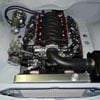
With the 434 SBC being fitted in the close future (I sold the first Shafiroff one to a mate), I ordered a Coan racing TH350 with all the fruit necessary for handling the torque.

When it arrived, I noticed that there was no speedo drive output fitted at all !  Time to start thinking about GPS speedo's.


SL cluster next to a SLR cluster


IMG_0408_zps586f710e.jpg


IMG_0407_zps99a9796a.jpg


Now the cluster build begins.....


#2 _434LX_

_434LX_
  • Guests

Posted 06 November 2014 - 10:33 PM

STRIPPING THE SL CLUSTER


The first step (once the cluster is out of the car) is to prepare it for the new internals.


Remove the 6 screws on the front to remove the cover.


IMG_1996_zps9285d476.jpg


Next, remove the top cover, exposing the gauges.


IMG_1997_zps2286ba08.jpg


I used a sharpie pen to mark to level of the original gauge, so the new ones will sit properly.


IMG_1998_zps7d5b4fef.jpg


Center lines of the needles were also marked to help with alignment.


IMG_2002_zps62a24354.jpg


#3 _434LX_

_434LX_
  • Guests

Posted 06 November 2014 - 10:41 PM

STRIPPING THE SL CLUSTER - cont


Flip the cluster over and remove the 2 screw that hold the speedo in place.


IMG_1999_zps265229d3.jpg


The speedo can now be removed.


IMG_2001_zpsfc22c57f.jpg


Next, make sure the center line of the clock is marked. This is going to be a tacho in my new cluster.


IMG_2004_zpsf1621578.jpg


Remove the 3 screws shown for the clock.


IMG_2003_zps2227cfdd.jpg


The clock can now be removed


IMG_2005_zps68263936.jpg


#4 Mort

Mort

    Lotsa Posts!

  • Members
  • PipPipPipPipPipPip
  • 2,760 posts
  • Name:Mort
  • Location:Moranbah, QLD.
  • Car:74 LH SL/R 4.2, 75 LH 4 door 186
  • Joined: 16-December 07
Garage View Garage

Posted 06 November 2014 - 10:42 PM

Top idea Andrew   :spoton:  :spoton: , i am interested in this so gave you a like for it and following so i don't miss any updates.


Don't know how you will go about it but could i suggest you put up a parts list with part numbers, place to purchase and if not a problem a price of parts,

i understand that prices will differ state by state, town/city by town/city, it would be good for a referance and not only that, your price might be cheaper than what we get.


#5 _434LX_

_434LX_
  • Guests

Posted 06 November 2014 - 11:02 PM

TIDY UP THE STOCK WIRING


Next, flip the cluster back over and we can start to tidy up all the redundant wires.

Remove the 2 screws that hold the harness plug in place.


IMG_2006_zps90895222.jpg


With the plug clear of the cluster, we can decide on what stays and what gets the chop !


IMG_2010_zpsbd25f403.jpg


My project may differ to anyone else's, so dont blindly copy this. Consult a wiring diagram and plan what you want to do first.


harness_zps91d49fc1.jpg


I want to retain high beam, LH / RH indicators, the fuel gauge, illumination and the brake warning light. The fuel gauge requires the voltage stabiliser to be retained also.

And dont forget the retain the earth !


#6 _434LX_

_434LX_
  • Guests

Posted 06 November 2014 - 11:11 PM

TIDY UP THE STOCK WIRING - cont.


Take your trusty snips and remove those unwanted wires


IMG_2007_zps2c404b84.jpg


IMG_2008_zps3425fbf4.jpg


You should end up with a much neater harness. We will come back to this bit later...


IMG_2011_zps96aa8f56.jpg


I have also removed all the rear illumination as it is redundant for my project.


#7 _434LX_

_434LX_
  • Guests

Posted 06 November 2014 - 11:13 PM

Top idea Andrew   :spoton:  :spoton: , i am interested in this so gave you a like for it and following so i don't miss any updates.


Don't know how you will go about it but could i suggest you put up a parts list with part numbers, place to purchase and if not a problem a price of parts,

i understand that prices will differ state by state, town/city by town/city, it would be good for a referance and not only that, your price might be cheaper than what we get.


Thanks Mort, this is a fairly complex conversion with a lot of custom parts.

I will show it beginning to end, but it wont be for the faint hearted LOL


#8 Mort

Mort

    Lotsa Posts!

  • Members
  • PipPipPipPipPipPip
  • 2,760 posts
  • Name:Mort
  • Location:Moranbah, QLD.
  • Car:74 LH SL/R 4.2, 75 LH 4 door 186
  • Joined: 16-December 07
Garage View Garage

Posted 06 November 2014 - 11:20 PM

Cool, i'm up for a challenge. :D


Might have to invest in a decent soldering iron though.


Edited by Mort, 06 November 2014 - 11:21 PM.


#9 _434LX_

_434LX_
  • Guests

Posted 06 November 2014 - 11:25 PM

REMOVE THE FUEL GAUGE


Next on the list is to remove the fuel gauge. I will be re-using the gauge on the new cluster fascia.

Undo the 2 nuts under the harness plug (easy while the plug is unscrewed)


IMG_2022_zpsd06d24a5.jpg


Undo the small screw at the base of the gauge fascia plate


IMG_2023_zps55522164.jpg


The gauge will lift out leaving the warning light inserts behind


IMG_2024_zps88adff46.jpg


#10 _434LX_

_434LX_
  • Guests

Posted 06 November 2014 - 11:54 PM

MEASURE AND DESIGN


My next step was to take several measurements of the empty cluster and work out a basic layout of what I wanted.


IMG_0718_zps9d26f636.jpg


IMG_0717_zps1e0cd1c4.jpg


This included accurate measurements of the removed components also


IMG_0719_zps252acf2a.jpg


I ended up with a massive pile of measurements and sat down to start a basic design in Autocad.

This is my first prototype


DashCAD_zpsce4d7adf.jpg


The only was I was going to tell if this was going to fit was to head of to the laser cutters and make a sample.


IMG_0720_zpsd8deb495.jpg


#11 _434LX_

_434LX_
  • Guests

Posted 06 November 2014 - 11:57 PM

And as luck would have it, it fits perfectly !


IMG_0721_zps26e04107.jpg


#12 _434LX_

_434LX_
  • Guests

Posted 07 November 2014 - 12:16 AM

ELECTRONIC GAUGE SELECTION


For my gauges, I decided on Speedhut. Simply for their quality, price and compact size.

After a bit of measuring and a few emails, I worked out that the 4" gauges should do the trick nicely.


GPS Speedo  http://www.speedhut....-and-high-beam)


Speed_zps20c0f4bd.jpg


Shift light Tach  http://www.speedhut....RPM-Shift-light


tach_zps1d28dc41.jpg


Now, there has been a bit of discussion on GPS speedo's before on the forum.


Are they legal ?  -  Who cares, no cop will ever be able to tell the difference.

Do they work around tall buildings ? - Yes, I have tested this unit sitting on the dash of my late model landcruiser for two months. It works everywhere except through tunnels.

Is it accurate ? - Fark yes !  Even if you change diff ratio or tyre size it will be spot on


#13 ls2lxhatch

ls2lxhatch

  • Members
  • PipPipPipPipPipPipPip
  • 5,329 posts
  • Location:Perth
  • Car:LX Hatch
  • Joined: 29-May 06

Posted 07 November 2014 - 12:17 AM

Looks like you are off to a good start. I recommend you replace the mechanical factory voltage regulator with an electronic voltage regulator while you are at it. The factory regulators have been known to fail and cook the gauges.


Edited by ls2lxhatch, 07 November 2014 - 12:17 AM.


#14 _434LX_

_434LX_
  • Guests

Posted 07 November 2014 - 12:29 AM

TACHO


Now I haven't come this far, just to whack the gauges straight into my fascia and end up with a half assed job, so lets strip these bad boys down.

* Disassembling of your Speedhut gauge should be done at your own risk, your warranty will be void * 


Brand new it looks like this.


IMG_2418_zps11db827c.jpg


Unscrew the silver bezel and remove the glass carefully


IMG_2419_zps4215b64e.jpg


Remove the spacer ring


IMG_2420_zpsb0fa392c.jpg


Remove the gauge fascia and circuit board


IMG_2421_zps28d831a6.jpg


Poke the smaller plugs through the grommet


IMG_2422_zpsa7745170.jpg


Cut off the large plug


IMG_2423_zpse171fc7e.jpg


Looks like you are off to a good start. I recommend you replace the mechanical factory voltage regulator with an electronic voltage regulator while you are at it. The factory regulators have been known to fail and cook the gauges.


Good thinking Andy !


#15 _434LX_

_434LX_
  • Guests

Posted 07 November 2014 - 12:35 AM

TACHO - cont.


Check out how thin these gauges really are !


IMG_2424_zpsc14db8f0.jpg


They use a stepper motor to drive the needle


IMG_2425_zps51c0a828.jpg


A quick check and the 4" gauge is looking spot on


IMG_2427_zpsdb9f8f6d.jpg


A small piece of cloth and a fork pops the needle off. Be careful not to break the needle !


IMG_2428_zps45d5d3f9.jpg


#16 _434LX_

_434LX_
  • Guests

Posted 07 November 2014 - 12:42 AM

TACHO - cont.


Lift up the fascia taking note of the ribbon cable.


IMG_2429_zps7aa84e62.jpg


The cable unplugs from the circuit board easily


IMG_2430_zpse3396682.jpg


Remove the inner spacer ring and keep it for later use


IMG_2431_zps580d0d9d.jpg


Comparing gauge face to cluster window


IMG_2433_zps8cb2729f.jpg


Comparing gauge face to clock face


IMG_2434_zpsee3151d4.jpg


#17 _434LX_

_434LX_
  • Guests

Posted 07 November 2014 - 11:25 AM

SPEEDO


Now we want to strip the Speedo unit down.

* Disassembling of your Speedhut gauge should be done at your own risk, your warranty will be void *


Out of the box it looks like this.


IMG_2459_zps3f5480fa.jpg


Remove the silver bezel


IMG_2462_zps25c1b984.jpg


Carefully remove the glass


IMG_2463_zps216ac869.jpg


Next out is the spacer ring


IMG_2464_zps45f7e28e.jpg


Finally, remove the gauge circuit board from the housing. The wires will withdraw easily.


IMG_2465_zps5694a823.jpg


#18 _434LX_

_434LX_
  • Guests

Posted 07 November 2014 - 11:35 AM

SPEEDO - cont.


The needle can be carefully removed with a piece of rag and a fork. Take care when doing this.


IMG_2466_zps626408d0.jpg


Lift the gauge fascia from the circuit board so you can locate the ribbon cable.


IMG_2467_zpsdf656538.jpg


Remove the ribbon cable from the circuit board. The cable supplies power to the dial illumination, which I won't be using.


IMG_2468_zps86fc88eb.jpg


You are left with the gauge circuit board in all its glory. This model has a lcd screen which has the odometer display. It also has several other functions that you can read about on the

Speedhut link I supplied earlier. The gauge also has led's for indicator lights and high beam.


IMG_2469_zpscffb8959.jpg


The back shows the stepper motor for the needle and GPS aerial connector.


IMG_2470_zpsd9d8d870.jpg


#19 purrlx

purrlx

    Forum Fixture

  • Members
  • PipPipPipPipPip
  • 1,330 posts
  • Name:Danny
  • Location:Gladstone
  • Car:LX hatch
  • Joined: 23-December 11
Garage View Garage

Posted 07 November 2014 - 12:02 PM

Thats very impressive


#20 _434LX_

_434LX_
  • Guests

Posted 07 November 2014 - 12:17 PM

DASH CONCEPT


Now that I have the Speedhut gauge faces removed, I can work the position of the gauge circuit boards and where holes need to be cut.


IMG_2984_zps52e96aae.jpg


After a lot of measuring and calculations, it was back to Autocad to firm up a design that I would be happy with.

The only way to test it is to have a new template laser cut.


IMG_2982_zps8de3245d.jpg


And as there is a minimum cut cost, I made 10


IMG_2983_zpsef3ad835.jpg


A quick dummy fit into the cluster housing and I am happy.


IMG_2993_zpsd4915a22.jpg


IMG_2992_zps474b7d58.jpg


#21 _434LX_

_434LX_
  • Guests

Posted 07 November 2014 - 12:29 PM

DASH CONCEPT - cont.


The dial faces will be designed and printed onto a vinyl sticker that will be stuck onto the aluminum template.


My first step is to scan what I have.

You will notice that I have deleted the holes where the gauge buttons are located. As I dont want to drill holes in the clusters clear windows, I will relocate the buttons to under the dash.


img-X28110424-0001_zpsc4cbaf5f.jpg


From there I moved to photoshop to nut out my design.


dashconcept_zps991d8d30.jpg


Now the design concept is done, the details are off with a graphic artist to turn it into reality !


Edited by 434LX, 07 November 2014 - 12:29 PM.


#22 dattoman

dattoman

    Do I feel lucky? Well, do ya, punk?

  • Administrators
  • PipPipPipPipPipPipPip
  • 16,460 posts
  • Name:Neil
  • Location:Perth Western Australia
  • Car:LX SS , 76 Cadillac , 3 x dattos
  • Joined: 04-February 07

Posted 07 November 2014 - 08:22 PM

I like

I have plans for those speedhut gauges myself

Especially a GPS speedo that needs no connection to the box


Why didn't you go with a quad gauge for the last one ?


#23 _434LX_

_434LX_
  • Guests

Posted 07 November 2014 - 08:54 PM

I like

I have plans for those speedhut gauges myself

Especially a GPS speedo that needs no connection to the box


Why didn't you go with a quad gauge for the last one ?


I already have 2 capillary gauges for oil and temp (which I prefer over electric senders)

The quad gauge was considered, and probably would look good, but I like the 6 warning lights on the right.

I like to know what the temp actually is and how many PSI of oil pressure I have, not some indicative position on a dial.


#24 _434LX_

_434LX_
  • Guests

Posted 14 November 2014 - 07:26 PM

More updates coming soon :ph34r:


#25 _434LX_

_434LX_
  • Guests

Posted 19 January 2015 - 09:14 AM

This project is still going (for anyone who is following)


Have been let down by 2 graphic artists so far, so I'm still in search of a good one to finish the fascia.

Everything else is ready to go.....


Once this is done, I will be making a second version to suit the quad gauge also.

Thinking of selling these as a kit form or complete converted unit if there is any interest.


Edited by 434LX, 19 January 2015 - 09:17 AM.


1 user(s) are reading this topic

0 members, 1 guests, 0 anonymous users