Jump to content


Photo

Who has CAD Data for Torana stuff?


  • Please log in to reply
134 replies to this topic

#26 Bigfella237

Bigfella237

    Socially Distant

  • Members
  • PipPipPipPipPipPipPip
  • 4,371 posts
  • Name:Andrew
  • Location:Far South Coast of NSW
  • Car:(s) not as many as I'd like but more than I've got space for!
  • Joined: 31-October 14

Posted 02 July 2015 - 01:35 AM

I would love to see accurate measurements like that of LH/LX Torana chassis clips, I would be happy to do all the CAD work if somebody has the measurements? I was gonna do them myself but there's too many things in the way on a complete car, you'd need a bare shell, possibly on a rotisserie but I'm not sure if that would cause any distortion?


I want to CAD a front K-member plus upper & lower control arms as well but again. I don't have any bare examples to measure up.


I was also concerned about manufacturing tolerances, ie every car going together slightly different, but I thought everything could be "adjusted" to suit the official chassis checks as we went along?


should be able to find an engineer in nsw to cert the departure angle from the exhaust as VSB14 is an advisory document still here.


Ewww, I really don't want to open this can of worms again, and certainly not in this thread, but the departure angle rule is very much open to the individual engineer's interpretation, some may accept the exhaust as part of the "OEM permanent body work", some may not, but this has been argued to death on this forum several times at least and I'd really rather not go there again!


Re GrabCAD: This may be a limitation of the free Autodesk 123D software I'm using, but it seems to only import files in a *.svg format and the files on that website are *.stp or *.stl or *.SLDPRT, none of which this software seems to accept?


Is there a way to convert file formats?


I can see some advantage in being able to share files here, is there some common format or do all the different software packages just do their own thing?



#27 Sven

Sven

    Forum Participant

  • Members
  • PipPip
  • 31 posts
  • Name:Steven Goodwin
  • Location:Brisbane
  • Car:LX Torana
  • Joined: 17-November 14

Posted 02 July 2015 - 08:59 AM

*.svg?

I haven't heard of that one before.


*.stl - Stereo Lithography File

This is just a "skin", not a solid body, so most CAD programs cannot do much with this, except look at it.

Most 3D printers use an STL to make a physical product.


*.stp - STEP file

This is a dumb body that some CAD programs can still manipulate (slice, add to, change, etc.).


Another dumb body is *.x_t - Parasolid


Mostly the same as a STEP file, as in, can still manipulate the object.


I haven't used it, but I think *.SLDPRT might be a SolidWorks (CAD program) file. 


(EDIT - wish I would proof read my posts better before hitting the POST button)


Edited by Sven, 02 July 2015 - 09:02 AM.


#28 Bigfella237

Bigfella237

    Socially Distant

  • Members
  • PipPipPipPipPipPipPip
  • 4,371 posts
  • Name:Andrew
  • Location:Far South Coast of NSW
  • Car:(s) not as many as I'd like but more than I've got space for!
  • Joined: 31-October 14

Posted 02 July 2015 - 08:40 PM

Thanks Sven,


So maybe *.svg is only used by 123D?


Attached File  SVG file extension.JPG   112.67K   3 downloads


Hmm, so it looks like nobody wants to share their toys! I had hoped there was some universal language spoken but I guess not?


So say I want to take a design somewhere to have parts of a project made (CNC, laser, water jet, whatever), what file format would those kind of machines use?


#29 Sven

Sven

    Forum Participant

  • Members
  • PipPip
  • 31 posts
  • Name:Steven Goodwin
  • Location:Brisbane
  • Car:LX Torana
  • Joined: 17-November 14

Posted 02 July 2015 - 09:18 PM

For laser/water jet cutting, you are most likely making a flat sheet "something". A *.dxf is the most used file format that I am familiar with.

The subcontractor I have had parts CNC machined at, used *.stp
This was for timber patterns, to then make castings off.

#30 N/A-PWR

N/A-PWR

    CABIN ENGINE CONTROLS GALORE

  • Members
  • PipPipPipPipPipPipPip
  • 9,595 posts
  • Name:Dave I
  • Location:Wooroloo, 65km's East of Perth
  • Car:'1969' LC RAT TORANA
  • Joined: 08-December 12

Posted 02 July 2015 - 09:56 PM

.dxf is it


good stuff Steven.  :clap:


Edited by NA-PWR, 02 July 2015 - 09:55 PM.


#31 Bigfella237

Bigfella237

    Socially Distant

  • Members
  • PipPipPipPipPipPipPip
  • 4,371 posts
  • Name:Andrew
  • Location:Far South Coast of NSW
  • Car:(s) not as many as I'd like but more than I've got space for!
  • Joined: 31-October 14

Posted 02 July 2015 - 10:41 PM

The free 123D Design software I'm using will export to *.stl


If you pay for the premium version (US$9.99 per month on a subscription basis) it will also export to *.stp and "Create 2D Layout" (which I suspect may be a *.dxf file). Although I assume you could get all your plans drawn up, then pay one month's subscription and export them all at once?


The problem I have is that it will only import in this *.svg format, which nobody has ever heard of, but you get what you pay for I guess!


Back on the subject of 9" diff housings, for such a common thing it's proving extremely difficult to track down dimensions for. I did find this drawing of the bolt pattern in *.dxf format and then found a website to convert it to a *.png, I'll attach it here as it might come in handy for anyone thinking of designing something similar...


Attached File  ford-9-3rd-member.png   75.01K   3 downloads


...I also found this one...


Attached File  FORD_9_CASE_LAYOUT.jpg   94.38K   2 downloads


...and comparing the two they are both almost identical, a couple of the bolt holes end up a few thou different but I think that would be within an acceptable tolerance.


I still can't find any dimensions on the hole that the centre goes through in the front plate, but I think I'll grab a gasket from the local parts store next time I'm in there and measure that, should only cost a couple of bucks?


Also, if someone happens to know, is the 9" measurement the OD of the crownwheel or the diameter of the bolt circle? Would different gear sets have slightly different ODs? I'm trying to figure out how deep the housing has to be to accommodate any ratio that might get thrown in there.


#32 N/A-PWR

N/A-PWR

    CABIN ENGINE CONTROLS GALORE

  • Members
  • PipPipPipPipPipPipPip
  • 9,595 posts
  • Name:Dave I
  • Location:Wooroloo, 65km's East of Perth
  • Car:'1969' LC RAT TORANA
  • Joined: 08-December 12

Posted 02 July 2015 - 10:50 PM

I could be wrong Andrew,


but as far as I know,


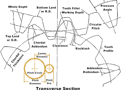
the diametre measurement,


is the common centre of a gear or 'Vee' belt pulley,


half way between the bottom and the top of the gear tooth or a pulley. 


220px-Internal_diameters.JPGsgw_profile.gif


True mesh or driven point.  :D


Edited by NA-PWR, 02 July 2015 - 10:56 PM.


#33 Bigfella237

Bigfella237

    Socially Distant

  • Members
  • PipPipPipPipPipPipPip
  • 4,371 posts
  • Name:Andrew
  • Location:Far South Coast of NSW
  • Car:(s) not as many as I'd like but more than I've got space for!
  • Joined: 31-October 14

Posted 02 July 2015 - 11:32 PM

Hmm... so how does that work out for a hypoid gear set?


I've never measured a crownwheel but I have an idea in the back of my brain that the 9" measurement is the bolt circle diameter, I just can't find anything on google to confirm?


EDIT: Alternately, does anyone have a 9" housing laying around that you can measure from the bolt-up-face to the deepest part of the back of the housing?


Edited by Bigfella237, 02 July 2015 - 11:37 PM.


#34 Bigfella237

Bigfella237

    Socially Distant

  • Members
  • PipPipPipPipPipPipPip
  • 4,371 posts
  • Name:Andrew
  • Location:Far South Coast of NSW
  • Car:(s) not as many as I'd like but more than I've got space for!
  • Joined: 31-October 14

Posted 03 July 2015 - 06:37 AM

As the old saying goes, it seems I couldn't see the forest for the trees before, I was too busy looking at importing files when I should have just tried opening them normally, turns out this software will happily open any of these file formats:


*.obj

*.sat

*.smb

*.stp

*.step

*.stl

*.123d


But will only save to the *.123d format, also it won't open a *.dxf file, I tried.


So anyway, I downloaded a full scale 9" carrier from GrabCAD and fitted it to the front plate design I have so far...


Attached File  9'' Carrier in Front Plate.JPG   43.47K   2 downloads


The bolt patterns seem to agree but there is a discrepancy between this carrier and the dimensions posted earlier, the housing is supposed to have a bolt-up-face to axle-centreline measurement of 1.675" but on this carrier it's 1.750", a difference of 75 thou or 1.9mm (slightly exaggerated looking down the axle tube in the pic below)...


Attached File  9'' Carrier Axle Centreline.JPG   25.93K   2 downloads


...this might be either to account for the gasket thickness (but that'd be a pretty thick gasket) or one of these measurements is incorrect, looks like more research needed there?


Also, this crownwheel measures exactly 9" OD but I've read online that there are also 9-1/4", 9-3/8" and 9-1/2" diameter crownwheels, so I wonder would there be any disadvantage to me allowing for say a 10" crownwheel (that would mean 1/4" (6.35mm) clearance between the biggest ring gear available and the housing, or a 1/2" clearance on the smallest)?


#35 76lxhatch

76lxhatch

    That was easy!

  • Members
  • PipPipPipPipPipPipPip
  • 7,152 posts
  • Location:Unzud
  • Car:SS
  • Joined: 04-August 08
Garage View Garage

Posted 03 July 2015 - 08:40 AM

SVG = Scalable Vector Graphics, which is an open format for vector drawings (even your browser will probably open one of these). It should be pretty common and work across many programs but its not really designed for detailed CAD drawings as such, its more of a generic graphics format.

#36 Bigfella237

Bigfella237

    Socially Distant

  • Members
  • PipPipPipPipPipPipPip
  • 4,371 posts
  • Name:Andrew
  • Location:Far South Coast of NSW
  • Car:(s) not as many as I'd like but more than I've got space for!
  • Joined: 31-October 14

Posted 04 July 2015 - 03:08 AM

I think I've created a monster with this diff project...


Attached File  9'' Carrier and Housing 01.JPG   47.91K   2 downloads


I still have a heap of things to finish, like adding some extra braces and struts inside, and I need to put in some baffles for oil control but I'm not exactly sure what to do there, as it stands the thing is gonna hold about 10 litres of oil, good for lubrication, bad for unsprung weight.


And of course I need to add a vent, filler & drain plugs, and I'll throw in a temp sensor bung and some AN fittings for an external oil pump/cooler too (just because I can). I was actually thinking about dry-sumping the thing with some internal squirters for lubrication, I wonder if that's ever been done? ;)


I'm also having trouble with some of the triangular panels, in that they're not perfectly flat. If I was actually welding this up it would just be a slight twist in the vice to get it to fit, but I don't know how to do that in CAD yet...


Attached File  9'' Carrier and Housing 02.JPG   34.61K   2 downloads


Not sure what to do with swingarm mounts yet either, that's a whole other ball of wax, but I plan to add some more external bracing around the outside of the housing once the mounting points are finalized, kind of sorta similar to a McDonald Bros diff (but I reckon my design would be tougher :P)...


Attached File  McDonald Bros diffhouse16.jpg   29.34K   3 downloads


From what I've been reading, chrome-moly would be the material of choice here, the face-plate is 3/8" thick, axle tubes are 3-1/4" OD 1/4" wall and the rest of the plate work is 1/8" thick, I reckon that should be pretty much indestructible.


For the sake of this exercise, I'm thinking about making it a coil-over, centred 3-link plus adjustable Watt's linkage (another CAD project in the wings) and of course provision for a sway bar (mounted to the car to keep the unsprung weight down so only link-points needed on the diff, obviously as far apart as possible).


#37 _Bomber Watson_

_Bomber Watson_
  • Guests

Posted 04 July 2015 - 01:45 PM

I hope you dont intend to put that under a Torana with any less than a 10" lift kit :D


#38 Bigfella237

Bigfella237

    Socially Distant

  • Members
  • PipPipPipPipPipPipPip
  • 4,371 posts
  • Name:Andrew
  • Location:Far South Coast of NSW
  • Car:(s) not as many as I'd like but more than I've got space for!
  • Joined: 31-October 14

Posted 05 July 2015 - 07:56 AM

Except for the braces that run out behind the axle tubes it shouldn't be any bigger than a standard 9" housing, if I refit the carrier and split the housing in half (so I can see inside), there's still bugger all clearance between the crownwheel and the back of the housing.


The problem would be in getting exhausts to run up over the axle tubes but a lot of people seem to run their exhausts under 9" diffs anyway. And yet another advantage of a centred 3-link suspension design is you get a lot more room for tail pipes as the original upper trailing arms and their mounts aren't in the way.


I need to do another 2D sketch but that whole back section should be able to be cut from one piece of steel and then folded, all except for 4 little triangular bits that weld to the tubes, although there may well be too much waste considering the price of chrome-moly?


It's funny browsing that GrabCAD website, there are some very talented people at using CAD that have no idea about engines, one guy I saw drew a V8 crankshaft but it had 8 individual journals (one conrod per), it must've been about 6 feet long?


I've been a bit disappointed though, I've been looking for generic CAD drawings to save myself some time, simple things like a selection of AN Fittings, but I've been coming up short, I did see a complete Holden one-tonner chassis over there though.


Edited by Bigfella237, 05 July 2015 - 07:56 AM.


#39 _Bomber Watson_

_Bomber Watson_
  • Guests

Posted 05 July 2015 - 06:05 PM

If you intend on using the stock suspension I'm pretty sire your uca mounts will be inside the top part of your fabricated housing, also I recon it would frOck with the floorpan royally if you wish to run any kinda tasteful ride height.

Could be by passable to an extent with a different suspension setup but I'm unfamiliar with your build parameters.

Cheers.

#40 Bigfella237

Bigfella237

    Socially Distant

  • Members
  • PipPipPipPipPipPipPip
  • 4,371 posts
  • Name:Andrew
  • Location:Far South Coast of NSW
  • Car:(s) not as many as I'd like but more than I've got space for!
  • Joined: 31-October 14

Posted 10 July 2015 - 01:36 PM

Still messing around learning how this CAD thing works, figuring out new little tips 'n tricks every day.


I started out trying to draw up a HQ front stub axle but ran out of dimensions, I find that's the hardest part, without going out and pulling something off a car to measure I'm just having heaps of trouble finding the necessary info to begin with. Anyway I somehow switched from a spindle to a drum brake hub and ended up turning out a few different versions of these...


Attached File  Holden Hub 5 on 4.75'' PCD 71.1mm Bore 01.JPG   40.26K   1 downloads


I did one with a Torana PCD, one with a HQ (pictured) and one with Commodore, all with the correct threads (7/16 x 20tpi for the first two and 12 x 1.5mm for the latter), it took me bloody ages to get all the thread pitches right but now that I look at it I think I got the dimensions wrong on the wheel nut threads, or I used the size of the early nuts, might have to go back and fix that? Is HQ supposed to have 7/16" studs or 1/2"?


Attached File  Holden Hub 5 on 4.75'' PCD 71.1mm Bore 02.JPG   38.98K   3 downloads


Oh yeah, I found a way to convert most CAD file formats too using the "Workbench" over at the GrabCAD website, unfortunately it won't display nor convert these proprietary *.123d files though, which kinda sucks because it means I still can't export files that any other software can use.


#41 _Bomber Watson_

_Bomber Watson_
  • Guests

Posted 10 July 2015 - 06:06 PM

Your getting pretty good.

HQ is 7/16".

#42 Bigfella237

Bigfella237

    Socially Distant

  • Members
  • PipPipPipPipPipPipPip
  • 4,371 posts
  • Name:Andrew
  • Location:Far South Coast of NSW
  • Car:(s) not as many as I'd like but more than I've got space for!
  • Joined: 31-October 14

Posted 11 July 2015 - 06:40 AM

Talk about a "plastic engine"!


This is not really CAD-related but I found a company in the US (P-Ayr) making polyurethane foam motors for dummy fitting engine conversions...


Attached File  pyp-2046_w_xl.jpg   147.75K   0 downloads


Every threaded hole you'd find in an OEM block is reproduced with a steel insert, all factory accessories bolt up (including sump and bellhousing) and the heads are even removable, it's just a shame they cost about the same as you can buy a motor from a wrecker!


But still, if you were doing conversions all the time it'd have to be a lot easier on the back.


#43 Bigfella237

Bigfella237

    Socially Distant

  • Members
  • PipPipPipPipPipPipPip
  • 4,371 posts
  • Name:Andrew
  • Location:Far South Coast of NSW
  • Car:(s) not as many as I'd like but more than I've got space for!
  • Joined: 31-October 14

Posted 11 July 2015 - 07:18 PM

What a way to spend half a weekend...


Attached File  Floater Assy 2.JPG   30.73K   2 downloads


Attached File  Floater Assy 3.JPG   61.06K   0 downloads


Attached File  Floater Assy 4.JPG   39.22K   0 downloads


It's based on the Strange Engineering F5010 Pro Touring Floater Kit but as usual I had trouble getting a full set of dimensions, I know the length is spot on but I had to take my best guess with some of the diameters, the spindle, drive plate and cap should be close but the hub is mostly based on photos, but I won't lose any sleep over that.


The real version is multi-drilled for three different stud patterns too but I only did 5 x 4.75", it looks like Swiss cheese with all those holes, and I couldn't be bothered doing the wheel bearings and seal although I did see one of the bearing manufacturers had ready-made CAD drawings on their website, it's a pity more companies don't do that.


I still have to do the hat, rotor, caliper and mount but I might be able to cheat and download something there?


I achieved my objective anyway, which was figuring out the lengths needed for the axle tubes and axles on the diff housing I was working on, 35 spline all around just for the hell of it (and yes, there are exactly 35 splines in the drive plate above)!


#44 Bigfella237

Bigfella237

    Socially Distant

  • Members
  • PipPipPipPipPipPipPip
  • 4,371 posts
  • Name:Andrew
  • Location:Far South Coast of NSW
  • Car:(s) not as many as I'd like but more than I've got space for!
  • Joined: 31-October 14

Posted 12 July 2015 - 02:21 PM

Ever more complicated (and colours now too)...


Attached File  Floater Assy 5.JPG   66.13K   1 downloads


Attached File  Floater Assy 6.JPG   55.74K   4 downloads


The new additions are based on the Wilwood 140-12436-DR kit that apparently suits Strange Engineering's floater kit.


I had to redo the bearing hub section because I had the wrong measurements for the bolts that hold the rotor hat too, I still don't think that part is 100% accurate but I'm only really mucking around anyway. Just the caliper and mounting bracket to go!


P.S. What a PITA it was to do that brake rotor, 72 bloody vanes and every single one got a ventilation hole!


P.P.S. I need to find an accurate wheel rim somewhere too (I'll probably end up drawing one up myself) but it looks to me like you could easily space the rotor and caliper inward with this setup, radial size should be okay as Wilwood say this brake kit suits 17" wheels but if you had trouble with the centre piece of the rim, as in Simmons which dish the wrong way, I reckon it wouldn't be too hard to get around with the above, well on the rear anyway?


#45 Sven

Sven

    Forum Participant

  • Members
  • PipPip
  • 31 posts
  • Name:Steven Goodwin
  • Location:Brisbane
  • Car:LX Torana
  • Joined: 17-November 14

Posted 12 July 2015 - 03:06 PM

Did you draw 72 individual vanes, or draw one vane and array it around another 71 times?

#46 Bigfella237

Bigfella237

    Socially Distant

  • Members
  • PipPipPipPipPipPipPip
  • 4,371 posts
  • Name:Andrew
  • Location:Far South Coast of NSW
  • Car:(s) not as many as I'd like but more than I've got space for!
  • Joined: 31-October 14

Posted 12 July 2015 - 03:33 PM

Yep you just draw one and revolve it around the sketch, it was the design that took some trial 'n error.


There are 36 holes in each side of the disc and each set of holes is 'timed' 15° (or 3 vanes) off the set on the other side, buggered if I know if that's important as I noticed Wilwood doesn't even do that, their holes are drilled straight through from one side to the other and half the vanes don't get holes at all?


BTW, that's a left hand (passenger's side) disc, if you wanted a pair you'd have to draw the whole thing over again with the curved vanes running the other way, but I don't think I'll be doing that any time soon!


I had another idea after posting too in that I might design a backing plate with a little air scoop that hangs down under the axle tube to blow some fresh air into the rear discs, although I don't know how good the air quality is gonna be under there with heat from the engine/trans/exhaust and crap flung up by the front tyres might mean it's not worth it? Still, costs me nothing to think about it!


#47 N/A-PWR

N/A-PWR

    CABIN ENGINE CONTROLS GALORE

  • Members
  • PipPipPipPipPipPipPip
  • 9,595 posts
  • Name:Dave I
  • Location:Wooroloo, 65km's East of Perth
  • Car:'1969' LC RAT TORANA
  • Joined: 08-December 12

Posted 12 July 2015 - 03:38 PM

Great Cad 3D you have done Andrew,


in my readings,


it seems that the Racing guy's only have grooved discs,


and no holes, something to do with cracking? :furious:  


#48 Bigfella237

Bigfella237

    Socially Distant

  • Members
  • PipPipPipPipPipPipPip
  • 4,371 posts
  • Name:Andrew
  • Location:Far South Coast of NSW
  • Car:(s) not as many as I'd like but more than I've got space for!
  • Joined: 31-October 14

Posted 12 July 2015 - 03:49 PM

Yeah I notice these fish-hook or "J" shaped grooves seem to be the in thing lately.


I found some engineer's thesis online a while ago, the entire thing was on brake cooling but it was like 700 pages long and very heavy reading so I didn't get that far into it, but this person setup all these tests in a wind tunnel and tested everything known to man in the way of different disc and pad materials, shapes, sizes, vanes, holes, slots, etc.etc., unfortunately it would've taken me a week of reading to figure out what his conclusions were!


#49 Bigfella237

Bigfella237

    Socially Distant

  • Members
  • PipPipPipPipPipPipPip
  • 4,371 posts
  • Name:Andrew
  • Location:Far South Coast of NSW
  • Car:(s) not as many as I'd like but more than I've got space for!
  • Joined: 31-October 14

Posted 12 July 2015 - 04:12 PM

You would think so but I don't seem to be able to find such a function in this free software?


Actually now that I think about it, I could just flip the 2D sketch over and extrude it from the other side, I can't see why that wouldn't work? But I only need one for now anyway, if I get really bored later I might knock one out and store it away, but I can't see that happening soon!


#50 Sven

Sven

    Forum Participant

  • Members
  • PipPip
  • 31 posts
  • Name:Steven Goodwin
  • Location:Brisbane
  • Car:LX Torana
  • Joined: 17-November 14

Posted 12 July 2015 - 04:18 PM

Are you creating each part as a separate model and importing each model into the assembly, or drawing everything in the one model? I only ask, as I'm not familiar with the cad package your using and what it can do.


0 user(s) are reading this topic

0 members, 0 guests, 0 anonymous users