
Maybe. ;-)

Who has CAD Data for Torana stuff?
Started by
Heath
, Jun 26 2015 01:19 PM
134 replies to this topic
#101

Sven
-

- Members
-

- 31 posts
Forum Participant
- Name:Steven Goodwin
- Location:Brisbane
- Car:LX Torana
- Joined: 17-November 14
Posted 28 July 2015 - 09:48 PM
#102
Heath
 View Garage
-
- Administrators
-
- 18,309 posts
I like cars.
- Name:Heath
- Location:Eastern Suburbs, Melbourne
- Car:Heavily Modified UC Sunbird Hatchback
- Joined: 07-November 05
View Garage
Posted 28 July 2015 - 10:03 PM
Sorry to hear.
Not too much of that equipment in Australia lol
Edited by Heath, 28 July 2015 - 10:04 PM.
#103
Bigfella237
-

- Members
-
- 4,371 posts
Socially Distant
- Name:Andrew
- Location:Far South Coast of NSW
- Car:(s) not as many as I'd like but more than I've got space for!
- Joined: 31-October 14
Posted 29 July 2015 - 01:14 AM
If anyone actually ever uses this Torana chassis diagram to check their car, I strongly suggest using the imperial measurements as it seems the plan was done in inches and then converted, the metric figures don't quite add up...
 90704_Torrie_Body_Spec_s_122_495lo.jpg 210.86K
11 downloads
90704_Torrie_Body_Spec_s_122_495lo.jpg 210.86K
11 downloads
I re-drew the basic plan twice, once using the imperial figures given...
Torana Chassis (drawn in inches).JPG 111.55K
4 downloads
...and again using the metric figures given...
Torana Chassis (drawn in millimetres).JPG 101.96K
5 downloads
...or maybe the difference is because they haven't rounded-down properly?
Either way you draw it that rearmost diagonal doesn't quite work out either. Although I guess most people crawling around under their car with a tape measure aren't going to tell the difference of 0.651 of a millimetre?
I suppose GMH would've been lucky to have a computer of any kind back in the mid 70's let alone CAD software so I'll let 'em off on this one!
#104
Rockoz
-

- Members
-
- 3,965 posts
Lotsa Posts!
- Name:Rob
- Location:Cowra NSW
- Joined: 21-September 08
Posted 29 July 2015 - 07:11 PM
Would have been lucky to have been within 5 mm anyway
#105
Bigfella237
-
- Members
-
- 4,371 posts
Socially Distant
- Name:Andrew
- Location:Far South Coast of NSW
- Car:(s) not as many as I'd like but more than I've got space for!
- Joined: 31-October 14
Posted 31 July 2015 - 02:28 PM
Some more tinkering around with "Badge Engineering" (or should that be "Badge Reverse-engineering")...
TORANA A9X Emblem.JPG 85.42K
4 downloads
..based on this sticker...
Torana.jpg 87.25K
7 downloads
I believe one of the Torana books has a picture of a proposed "A9X" sticker that arrived too late to be fitted but I don't have that book nor could I find a picture of it so I just took my best guess with that part, used the same "A" and modeled the "9" off the "R", but the "X" is pure fiction!
If anyone has a picture of the genuine "A9X" sticker please post it here?


#107
Bigfella237
-
- Members
-
- 4,371 posts
Socially Distant
- Name:Andrew
- Location:Far South Coast of NSW
- Car:(s) not as many as I'd like but more than I've got space for!
- Joined: 31-October 14
Posted 31 July 2015 - 02:54 PM
Ah, just realised I never updated the handbrake assy pics, just about done all I can do for now...
Handbrake Assy 06.JPG 57.82K
4 downloads
Threw in the adjustable proportioning valve and drew up a Wilwood electric line lock valve too just for the hell of it, added some quick brake lines and Bob's your aunty!
Next thing I'm working on is a combined coolant surge tank slash overflow tank slash windscreen washer bottle slash whatever else I can squeeze in to replace the heater fan and duct in the engine bay.
Haven't settled on a design yet but I want it to kinda balance out the look of the brake booster on the other side.
#108
Bigfella237
-
- Members
-
- 4,371 posts
Socially Distant
- Name:Andrew
- Location:Far South Coast of NSW
- Car:(s) not as many as I'd like but more than I've got space for!
- Joined: 31-October 14
Posted 11 August 2015 - 05:47 AM
Been working on a heap of different CAD projects lately but there doesn't seem to be much interest in this thread so I haven't bothered updating it, anyway, I finally circled back around to my rear suspension setup over the weekend so I thought I'd round out the project.
This probably belongs more in the Radical Rear Suspension thread but the rest of the bits are here so...
Rear Suspension 03.JPG 135.77K
6 downloads
I never bothered to work out the rocker ratios so I suspect they are completely wrong, but it's a reasonably simple change to make later, I just have to vary the distance between the coil-overs and the length of the central sway bar to suit.
BTW, I nearly fell off my perch when I saw the price of those adjustable sway bar blades @ 350 USD EACH!
Still wondering if it's worth having the remote adjusters in the cabin, I wouldn't have the big ugly-looking levers in a road car but they do make a "Vernier-style" cable that twists and pulls like a hand-throttle, maybe I could hide them around the handbrake / centre console area somewhere? It's not like I'd ever be "tuning" to that degree anyway but might be worth it for the fap-factor!
Height-wise I think these two new crossmembers will sit on top of the OEM chassis rails and I've resigned myself to cutting out the centre of the factory spring saddles and most of the floorpan over the diff, but if I tie everything back into the stock rails fore & aft and re-sheet the floor over the top I should be good (and still not an ICV with any luck). I'm confident all of the above should still fit under the tonneau floor (don't ask me what you'd do in a sedan).
The only thing that's really gonna suck is shock and spring adjustments, I'm wondering if I can have some kind of removable inspection plate(s) so I could get to them from inside for initial setup at least, maybe with the rear seats temporarily removed (without the factory UCA mounts there should be nothing in the way)?
Actually, I was wondering if you'd be allowed to have a clear polycarbonate section in the boot floor so all of this can be on display instead of just hidden away under the car!
Another important goal was still being able to get a decent exhaust system through to the rear of the car and I think I might actually just have room...
Rear Suspension 02.JPG 65.09K
1 downloads
...although it's still gonna be tight over that RH Watts Linkage depending on where the rear RC ends up being adjusted, I was thinking about making a link that isn't straight but takes a dog-leg downward, I can't see it would matter what shape it was so long as the pivots stay in the same place, and it doesn't flex of course?
Stupid thing is, I started all this so I wouldn't have to cut through the floor to mount the coil-overs up so high... I guess that didn't really work out after all... as it happens I could pretty much leave that upper cross member where it is and simply bolt the shocks 'upright' between it and the diff anyway, which I may well end up doing still, I'd just have to re-design the sway bar, which is easy peasy.
#109
_Bomber Watson_
_Bomber Watson_
-

- Guests
Posted 11 August 2015 - 09:22 AM
I really want one of those handbrakes....
#110
Bigfella237
-
- Members
-
- 4,371 posts
Socially Distant
- Name:Andrew
- Location:Far South Coast of NSW
- Car:(s) not as many as I'd like but more than I've got space for!
- Joined: 31-October 14
Posted 31 January 2017 - 05:58 PM
A little something for Bomber...

#111
Shiney005
View Garage
-

- Members
-
- 9,034 posts
Oh My, Don't you post alot
- Name:Laurie
- Location:Dubya Hay
- Car:Toyota Mirai
- Joined: 19-January 12
View Garage
Posted 31 January 2017 - 11:18 PM
It won't be too long and it will be cheap enough to 3D print one of those out of titanium.
#112
Bigfella237
-
- Members
-
- 4,371 posts
Socially Distant
- Name:Andrew
- Location:Far South Coast of NSW
- Car:(s) not as many as I'd like but more than I've got space for!
- Joined: 31-October 14
Posted 01 February 2017 - 03:48 PM
I can't wait! I've actually been looking at some of these "desktop machines" lately like BoXZY, which is a three-in-one 3D printer, 3-axis CNC Mill, and LASER cutter...
...that was the kickstarter video but they're now for sale at US$3000, just not sure if that money would be better spent on a stand-alone professional mill, it looks like a bit of a 'toy'?
And I think I'd really miss the 4th and even 5th axis of a 'proper' CNC mill, especially when dealing with larger projects, like making my own wheel rim centres?
#113
Shiney005
View Garage
-
- Members
-
- 9,034 posts
Oh My, Don't you post alot
- Name:Laurie
- Location:Dubya Hay
- Car:Toyota Mirai
- Joined: 19-January 12
View Garage
Posted 02 February 2017 - 08:58 AM
Amazing! The Chinese will have one of these with a 5 axis cnc and without the need to change tools for even less money in a couple of years.
#114
Bigfella237
-
- Members
-
- 4,371 posts
Socially Distant
- Name:Andrew
- Location:Far South Coast of NSW
- Car:(s) not as many as I'd like but more than I've got space for!
- Joined: 31-October 14
Posted 12 May 2017 - 08:14 PM
I find pictures like this amazing...
Bearing and Seal 01.JPG 182.47K
4 downloads
...why you ask? Only because this bearing and seal doesn't actually exist, I drew them both in CAD!
As may be evident, I've graduated from that old 'free' AutoDesk CAD software that I started with, to Solidworks. It's been a whole 'nuther experience learning the new software but some of the things this new program can do is mind boggling.
My main problem I have now is that my current PC is just way too under-powered, it took over 20 minutes to render the above picture for example, and that's only when it doesn't freeze-up and quit the process altogether. I really need to build a new PC with a couple of powerful graphics cards but my budget doesn't allow right now.
My other problem is that I couldn't transfer any of my old CAD models from 123D to Solidworks (well, not without paying for a subscription to the old software anyway), but having to redraw everything has at least gotten me (somewhat) up to speed with how Solidworks does things.
The whole "mates" thing is new to me as the old software didn't allow relative movement, but very interesting once you get the hang of it. That bearing for example works as it would in real life, I can turn the inner race and the rollers roll and the cage rotates at half the speed... I tried to do a motion study where you can record video of it in action, but my PC had a hernia and it turned out all jerky.
Getting back to the handbrake project above, it continues to evolve as well. Although I keep changing my mind about whether to have the hydraulics 'stand-alone' (as pictured earlier with a dedicated reservoir) or 'in-line' (negating the requirement for an extra set of rear brake calipers). All the designs since the above have gone back to the in-line philosophy, however I keep finding other things to add and it's gettin' a little busy at the back...
Handbrake V3 01.JPG 71.97K
2 downloads
...stuff like a fire handle and the vernier adjusters for the front & rear sway bars, although they were always part of the plan, along with the brake bias and line-lock valves of course.
Perhaps the best thing I love about Solidworks is how easily you can go back and make changes, the old software basically required you continue to modify the model, rather than being able to step back in time and 'change the past'... if only it would allow me to go forward in time and see how it turns out before I design it? 
And of course work continues on my custom rear axle housing...
Rear Differential Assy 08.JPG 41.93K
2 downloads
...but the rest of the rear suspension isn't anywhere near back to where it was in the old CAD yet, I've drawn the Watt's Link but still haven't gotten around to the rest yet.
There's so many other things I've been drawing-up in between as well, like tyres for example...
Kumho KU36 - Rear Tyre 06.JPG 36.78K
2 downloads
...but I just couldn't show them all cause it'd take this old PC forever to render them... however donations to the cause will be gladly accepted and rewards forthcoming. 
This is kinda like art for the artistically challenged!
#116
Bigfella237
-
- Members
-
- 4,371 posts
Socially Distant
- Name:Andrew
- Location:Far South Coast of NSW
- Car:(s) not as many as I'd like but more than I've got space for!
- Joined: 31-October 14
Posted 09 August 2017 - 04:55 PM
Does anyone happen to have a CAD model of a Simmons wheel?
I'm specifically looking for either an FR-17 or OM-17 centre piece, but I'll take anything Simmons really?
#117
_Bomber Watson_
_Bomber Watson_
-
- Guests
Posted 09 August 2017 - 07:40 PM
Been a while since i've looked in here.
Thats all frOcking awesome.
I still want the handbrake 
#118
Cook
-

- Members
-
- 1,504 posts
Forum Fixture
- Location:Melbourne
- Car:LX Hatch
- Joined: 27-February 15
Posted 09 August 2017 - 08:05 PM
Hi Andrew, I am looking to run a serpentine system in the Hatch and had spoken with Daniel at Reidspeed about making the bracketry to allow for the alt (driver side) and air compressor (pass side) similar to what they have for the Holden power steering/alt as per the pic but he isn't interested in proceeding with it. I want it so that the alt and compressor sit just above the chassis rails. I believe that one of the issues is weight of the compressor, particularly where you are using aluminium. So my question is, how difficult/easy is this to design and how does this get translated into engineering acceptability and thereafter practicality/production. I just reckon there would be a reasonable level of demand, but I may be wrong. Cheers Ron
Attached Files
-
Aircon and Alt Mounting System.jpg 141.3K
5 downloads
#119
grumpy xu1
-

- Members
-
- 2,809 posts
Lotsa Posts!
- Name:Gary
- Location:Queensland
- Car:lj xu1
- Joined: 01-February 10
Posted 09 August 2017 - 08:20 PM
Does anyone happen to have a CAD model of a Simmons wheel?
I'm specifically looking for either an FR-17 or OM-17 centre piece, but I'll take anything Simmons really?
You need to design a copy of the rat trap, that isn't a slopy piece of crap, but looks oem. You'd kill the market.
#120
Bigfella237
-
- Members
-
- 4,371 posts
Socially Distant
- Name:Andrew
- Location:Far South Coast of NSW
- Car:(s) not as many as I'd like but more than I've got space for!
- Joined: 31-October 14
Posted 09 August 2017 - 11:02 PM
G'day Ron, wow that bracket is a monster!
It actually seems like a huge waste of material to me, but I can also see the advantage of having everything mounted to a single bracket like that, no problems with alignment etc., but it must weigh a ton and cost a fortune?
Anyway... Designing the bracket wouldn't be that much work, but to do it in CAD you would first need to draw an accurate model of the Torana chassis rails, K-member, engine mounts, engine block, heads, crankshaft. water pump, oil pump & filter, etc. etc.
I've actually been meaning to do all that for a while for some other projects but it's a lot of work to get everything spot-on, and then you can't account for the differences from one car to another.
So I reckon that particular job would be easier done with a trusty old cardboard or wooden template, and then transferred to CAD once you had the basic shape figured out?
As for engineering acceptability, I don't think an engineer would need to know would they, so long as it had sufficient clearance to everything and wasn't going to self-destruct on the first pothole?
#121
Cook
-
- Members
-
- 1,504 posts
Forum Fixture
- Location:Melbourne
- Car:LX Hatch
- Joined: 27-February 15
Posted 10 August 2017 - 08:39 AM
Thanks Andrew. Gives me a good understanding of what would be required. I am a bit of a symmetry freak and I think something like that would look good and be practical given the serpentine system. It does look a bit cumbersome and I guess being made out of aluminium it is somewhat thick to obtain the required strength I presume. Their web site has a pic with it in a car and it isn't as noticeable with all the other parts around it. I think the face section wouldn't be that difficult to dummy up but the bracketry to support the alt and compressor would be the bits I don't understand. I was thinking engineering in terms of what you have said, something that won't collapse on the first run. LOL. Good luck with your endeavours and hope you find the Simmons wheels. Cheers Ron
#122
Bigfella237
-
- Members
-
- 4,371 posts
Socially Distant
- Name:Andrew
- Location:Far South Coast of NSW
- Car:(s) not as many as I'd like but more than I've got space for!
- Joined: 31-October 14
Posted 04 November 2017 - 06:15 PM
It won't be too long and it will be cheap enough to 3D print one of those out of titanium.
Oh if only I had a spare US$52k laying around...
#123
Bigfella237
-
- Members
-
- 4,371 posts
Socially Distant
- Name:Andrew
- Location:Far South Coast of NSW
- Car:(s) not as many as I'd like but more than I've got space for!
- Joined: 31-October 14
Posted 25 November 2017 - 12:42 PM
And now for something completely different...
Based on the theory that everything is better with velocity stacks (hmm?) I've been tinkering around in CAD again, this has nothing whatsoever to do with a Torana but may interest somebody...

I'm hoping that if I'm a really good boy for the next month that Santa might leave a 3D printer under the tree for me this year so I thought I'd design my own version of a fan upgrade for the print head in anticipation, of course it kinda got out of control like most things I do seem to, but it looks pretty cool none the less.
Or the six cylinder version for those that like a bit on the side...

When you compare that to the standard fan assembly it's clear the Chinese have no imagination whatsoever!
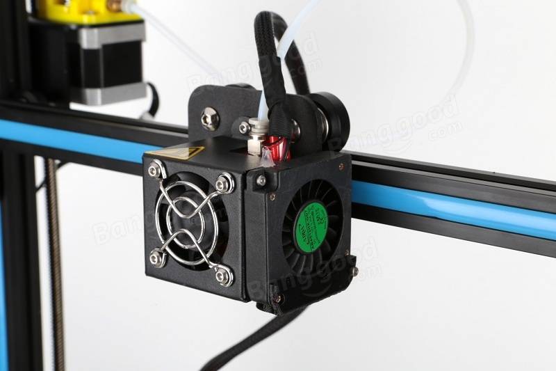
Anyhow, I thought I'd have a play around with this CFD Flow Simulation thingamajig too, not sure if I did it right but it looks pretty...

Don't ask me what any of that means, I'm just amazed that air seems to be coming out where it's supposed to be coming out and even flowing in the right direction!
I'd love to have a 3D model of a Torana, could be fun to look at the aerodynamics (or lack thereof)? One day I'll do one, but not until I get a faster computer than what I'm using now I can tell ya!
But back to 3D printers, I decided on the Chinese-made Creality CR-10 but I'm not sure which size to get yet. They come in three sizes ranging from 300x300x400mm up to 500mm cubed, and I'm pretty sure I'm gonna go for the biggest one, even though I could buy two of the smallest size for the same price.
BTW, 500mm cubed is big enough to print a 19" rim up to 19" wide... [insert evil laugh here]
#124
Bigfella237
-
- Members
-
- 4,371 posts
Socially Distant
- Name:Andrew
- Location:Far South Coast of NSW
- Car:(s) not as many as I'd like but more than I've got space for!
- Joined: 31-October 14
Posted 18 February 2018 - 09:42 PM
iceengineworks make the ultimate header modeling kit.
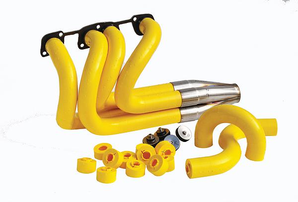
Why spend US$500+ when you have CAD and a 3D Printer...

...all the above are 2" OD, the bends are all 22.5° each (x4 = 90°) but the blue bends are 3" radius, the yellow are 4" radius and the red are 5" radius, and of course the green ones are straight ranging from ½" to 6" in length. The design came from a guy on Thingiverse but I ended up redrawing most of it myself.
I'm still looking for accurate dimensions on both types of Holden V8 header flanges if anyone has them handy?
I have plenty of older-style heads I could measure up (after I dig them out of my shed) but the only EFI heads I have are in my Statesman and I don't really feel like pulling that apart just to measure the ports.
BTW, if anyone is looking for dimension on just about anything American I found this website:
http://www.schoenfel...--gaskets4.html
Just click on each type of flange and it gives you a dimensional drawing.
#125
Bigfella237
-
- Members
-
- 4,371 posts
Socially Distant
- Name:Andrew
- Location:Far South Coast of NSW
- Car:(s) not as many as I'd like but more than I've got space for!
- Joined: 31-October 14
Posted 19 February 2018 - 07:14 PM
![]()
If the SL/R was the "Race" version of an SL, then shouldn't there be a...
![]()
...or maybe the resto-mod version would be...
![]()


0 user(s) are reading this topic
0 members, 0 guests, 0 anonymous users

