Jump to content


Photo

Coil / resistance wire in stock LX harness


  • Please log in to reply
30 replies to this topic

#1 308mate

308mate

    Forum Fixture

  • Members
  • PipPipPipPipPip
  • 523 posts
  • Name:scott
  • Location:Wootton - between Newcastle & Taree, NSW
  • Car:76 SS hatch (Royal Plum, Chevron Chamois interior), HQish Van (Orchid Metallic)
  • Joined: 19-May 09
Garage View Garage

Posted 30 June 2015 - 07:40 PM

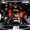
Tried to get my engine to run by using the stock yellow wire for the coil in a standard pollution wiring loom from NKA (ebay). I used a Bosch HEI coil and an MSD electronic dizzy....no way! Car wouldn't even idle.


Question: what is it about this power source that will not give enough juice to the coil?


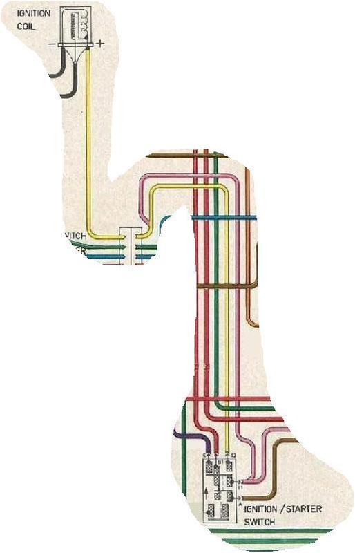
In the wiring diagram the yellow coil wire goes to the ignition switch on the steering column. Can I directly wire from the column to the fuse to get more volts or is the yellow wire a resistance (whatever that is) wire that will need to be replaced?


I want to try and use the standard loom if possible to try and keep things tidy.


#2 _Muzzy_

_Muzzy_
  • Guests

Posted 30 June 2015 - 08:08 PM

The coil supply wire will be a resistance type wire and most likely only provide 7-9 volts, this will vary depending on load , I would use the supply wire and use it to trigger a std relay this will provide 12-14 volts and the ability to cope with high current loads , the HEI dissy will pull 8 amps which is way too much for the poor stock wiring to cope with, I have done this on my Torana running the same coil and HEI dizzy as you

Edited by Muzzy, 30 June 2015 - 08:09 PM.


#3 UCSLE

UCSLE

    Forum Fixture

  • Members
  • PipPipPipPipPip
  • 702 posts
  • Name:troy
  • Location:perth
  • Car:Goggomobil
  • Joined: 23-June 09

Posted 30 June 2015 - 11:02 PM

the wiring loom from NKA , does it have a resistance type wire ? it should say in small print on the wire.

like muzzy said , its the wire it self in a stock loom


Just had a quick look on ebay , it looks like the nka wiring loom is wrong.

In a stock loom you have two power wires from the ignition switch to the coil , it looks to have only one .

Check to see if you have power to the coil with the ignition on and also when the engine is cranking .


#4 yel327

yel327

    Oh My, Don't you post alot

  • Members
  • PipPipPipPipPipPipPip
  • 13,072 posts
  • Joined: 10-February 08

Posted 01 July 2015 - 06:27 AM

As per above answers, normally you have 2 x wires: pink and yellow. One is start, the other is run. The run wire is the resistance wire. To fit a HEI I just short these two at the ignition switch plug, but the aftermarket loom may not have both.


#5 StephenSLR

StephenSLR

    Oh My, Don't you post alot

  • Members
  • PipPipPipPipPipPipPip
  • 6,707 posts
  • Name:Stephen
  • Location:Sydney
  • Car:1976 LX SL/R
  • Joined: 12-November 05

Posted 01 July 2015 - 08:49 AM

In the old days one option was to remove what my friend would call the 'ballast wire'; which is a wire of heavier resistance and replace it with a regular wire so that 12V can get through.


As mentioned in comments above the wire (I believe it was thicker) has a higher resistance and only allows 9V to get through.


^ this is what I was told; correct me if I'm wrong.


A simpler fix is to install a relay to provide 12V from the battery; you don't have to mess around removing and re-attaching wires from the stock loom to upgrade to electronic dizzies.


s


Edited by StephenSLR, 01 July 2015 - 08:51 AM.


#6 308mate

308mate

    Forum Fixture

  • Members
  • PipPipPipPipPip
  • 523 posts
  • Name:scott
  • Location:Wootton - between Newcastle & Taree, NSW
  • Car:76 SS hatch (Royal Plum, Chevron Chamois interior), HQish Van (Orchid Metallic)
  • Joined: 19-May 09
Garage View Garage

Posted 01 July 2015 - 12:54 PM

Thanks guys, appreciate the input. I've checked the NKA loom and the yellow coil wire has no writing that I can see to indicate wether its a resistance wire.


I've looked at the LH & LX supplementary wiring diagram an it does not indicate that there should be two wires to the + side of the coil....


#7 hanra

hanra

    Oh My, Don't you post alot

  • Members
  • PipPipPipPipPipPipPip
  • 10,831 posts
  • Name:Brad
  • Location:Farrrrrr North Qld
  • Car:1975 LH SL/R 5000, 1967 Morris Cooper S, E36 BMW, Toyota Corolla, Isuzu DMax
  • Joined: 24-March 11

Posted 01 July 2015 - 01:01 PM

Grab your multimeter and measure its resistance. Pink wire has full 12v when key in cranking/starting position. Yellow wire 9ish volts when running and key in ON position.


untitled_zpskgnxtaui.jpg


Edited by hanra, 01 July 2015 - 01:03 PM.


#8 yel327

yel327

    Oh My, Don't you post alot

  • Members
  • PipPipPipPipPipPipPip
  • 13,072 posts
  • Joined: 10-February 08

Posted 01 July 2015 - 01:04 PM

They'll be there, they run form the ignition switch to the engine harness connector plug on the firewall then only a single wire from there to the coil.


#9 tuxedoss

tuxedoss

    Forum Fixture

  • Members
  • PipPipPipPipPip
  • 1,024 posts
  • Name:Brett
  • Location:Sydney
  • Car:ss
  • Joined: 29-July 11

Posted 06 July 2015 - 03:52 PM

Isn't the loom off ebay just for the engine bay? As per Hanras picture there is only one wire there. The yellow resistance wire and normal pink wire are from the ignition switch to the firewall plug.

#10 _Macca97_

_Macca97_
  • Guests

Posted 06 July 2015 - 07:08 PM

im using the 9volt wire to switch a relay on for my fuel pump and later electronic dizzy, and ive found out that 9volts isn't enough to get the relay to close but once I hit the key and 12volts hits the relay, and the 9volts is enough to keep the relay closed


#11 EunUCh

EunUCh

    Lotsa Posts!

  • Members
  • PipPipPipPipPipPip
  • 2,761 posts
  • Location:not this planet
  • Car:japos
  • Joined: 23-November 06

Posted 06 July 2015 - 08:41 PM

^ that's because it takes a bit for the relay to "pull in" (lectronic talk), but once it has got over the initial "pull in" it will stay "latched" ...best find a take off  from a 12v 

switched source from the switched side somewhere,most relays only draw 200 milliamps give or take depending on the realy.


Hanras picture is correct , but...if the yellow wire is not connected to the coil and is measured with a multimeter it will read 12volts,you could have a Million OHM

resistor in line and it will still read 12V,could be a load thing?...as far as i know the voltage will read 9 volts approx. with the points closed ?


The current draw is not what it seems because when the points are closed it will give a reading of so many amps. , under running conditions this is not the case because it will come down to a mark/space ratio , or in modern terms "duty cycle" ,or, time on/time off with numbers ?


The beauty about lectronic stuff is that most of the modern stuff will run on a low voltage...where are those bloody Bosch training manuals?


#12 ben23

ben23

    Forum Member

  • Members
  • PipPipPip
  • 236 posts
  • Name:Ben
  • Location:Campbelltown, New South Wales
  • Car:'77 LX 2850 sedan
  • Joined: 02-October 14
Garage View Garage

Posted 09 July 2015 - 09:31 PM

The yellow wire between the coil pos and the engine side of the engine harness connector is yellow and is a normal wire, the resistance wire (Pink with "Resistance - Do Not Cut" printed on it in blue and the start bypass wire (Yellow) both run to the same terminal on the other side of the engine harness connector (the side going into the car). They run to two different positions on the ignition switch, the pink resistance wire to switched ignition and the yellow to a secondary start output (separate to the starter trigger (Purple). Easy way to bypass is to cut pink resistance wire at ignition switch and at the engine harness connector, cut yellow from ignition switch and splice it into the heavy pink wire from the ignition switch to the fuse box (or extend it, crimp on a female spade terminal and connect to a spare ignition terminal at the back of the fuse box. Would be a good time to fuse that wire too (10A should do it, or even connect it to the circuit that feeds the dash. ("tell-tales and reverse 15A" that fuse normally is)


#13 Dr Terry

Dr Terry

    Technical + Numbers Guru + Moderator

  • Moderators
  • PipPipPipPipPipPip
  • 3,276 posts
  • Location:Eastwood (Sydney) NSW
  • Joined: 13-November 05

Posted 10 July 2015 - 07:48 AM

The yellow wire between the coil pos and the engine side of the engine harness connector is yellow and is a normal wire, the resistance wire (Pink with "Resistance - Do Not Cut" printed on it in blue and the start bypass wire (Yellow) both run to the same terminal on the other side of the engine harness connector (the side going into the car). They run to two different positions on the ignition switch, the pink resistance wire to switched ignition and the yellow to a secondary start output (separate to the starter trigger (Purple). Easy way to bypass is to cut pink resistance wire at ignition switch and at the engine harness connector, cut yellow from ignition switch and splice it into the heavy pink wire from the ignition switch to the fuse box (or extend it, crimp on a female spade terminal and connect to a spare ignition terminal at the back of the fuse box. Would be a good time to fuse that wire too (10A should do it, or even connect it to the circuit that feeds the dash. ("tell-tales and reverse 15A" that fuse normally is)

Sorry ben23, that will not work properly.


If you cut the yellow & join it to the thick (pink) ignition supply wire, yes you will get a full 12V with IGN on, but you will have no 12V while cranking.


The simplest way to do it is to run a bridging wire from the yellow to the thick pink. I do it by shaving some insulation off both wires & soldering a short wire from yellow to thick pink.


This will give you a full 12V supply for both cranking & running, without the need for any relays or other stuff.


There is no need to cut the resistance wire, as it has been by-passed. Also if you wish to return the car to standard at a later date, simply cut the bridging wire.


Dr Terry


#14 ben23

ben23

    Forum Member

  • Members
  • PipPipPip
  • 236 posts
  • Name:Ben
  • Location:Campbelltown, New South Wales
  • Car:'77 LX 2850 sedan
  • Joined: 02-October 14
Garage View Garage

Posted 10 July 2015 - 11:05 PM

Could have sworn only accessories (brown) drops out under crank (otherwise warning lights and such would drop out under crank, which they don't), unless they are operating from feedback up the resistance wire under cranking. Been a little while since doing one. Trucks are what I do for a crust, got sick of playing with cars professionally haha.


#15 76lxhatch

76lxhatch

    That was easy!

  • Members
  • PipPipPipPipPipPipPip
  • 7,150 posts
  • Location:Unzud
  • Car:SS
  • Joined: 04-August 08
Garage View Garage

Posted 11 July 2015 - 07:34 AM

This seems to catch everyone out when doing engine conversions, the HQ-VK style ignition switch has two different circuits for START (crank) and ON. The yellow wire is START only, and the pink resistance wire is ON only. Obviously you need power to the coil in both positions, thus bridging them as Dr Terry says is the easiest solution. The only thing that can catch you out with this sometimes is if you have a big coil/ignition setup that needs a lot of juice with minimal voltage drop, the yellow wire isn't particularly big - hence the suggestions involving relays.

#16 308mate

308mate

    Forum Fixture

  • Members
  • PipPipPipPipPip
  • 523 posts
  • Name:scott
  • Location:Wootton - between Newcastle & Taree, NSW
  • Car:76 SS hatch (Royal Plum, Chevron Chamois interior), HQish Van (Orchid Metallic)
  • Joined: 19-May 09
Garage View Garage

Posted 11 July 2015 - 08:42 AM

I bridged the pink and yellow wires at the ignition switch and all worked fine. The second pink wire is my resistance wire. Thanks for your help on this one guys!

#17 Shiney005

Shiney005

    Oh My, Don't you post alot

  • Members
  • PipPipPipPipPipPipPip
  • 9,029 posts
  • Name:Laurie
  • Location:Dubya Hay
  • Car:Toyota Mirai
  • Joined: 19-January 12
Garage View Garage

Posted 11 July 2015 - 09:02 AM

Stupid question here. Why does the standard coil only require 9 volts whilst the engine is running? And can you hurt any part of the system by running a constant 12 volts through it?


#18 hanra

hanra

    Oh My, Don't you post alot

  • Members
  • PipPipPipPipPipPipPip
  • 10,831 posts
  • Name:Brad
  • Location:Farrrrrr North Qld
  • Car:1975 LH SL/R 5000, 1967 Morris Cooper S, E36 BMW, Toyota Corolla, Isuzu DMax
  • Joined: 24-March 11

Posted 11 July 2015 - 09:52 AM

Gives the points a bit of a longer lifespan. And having a system designed to run on 9v allows the points ignition system to operate during the cranking period.

Edited by hanra, 11 July 2015 - 09:56 AM.


#19 EunUCh

EunUCh

    Lotsa Posts!

  • Members
  • PipPipPipPipPipPip
  • 2,761 posts
  • Location:not this planet
  • Car:japos
  • Joined: 23-November 06

Posted 11 July 2015 - 02:52 PM

It's not such a stupid question and always an interesting point !


From my limited understanding...


The way i see it is that the coil has an internal resistance of say 1.2 ohms , with 13.2 volts across that resistance given if  the points were closed results in about 11 amps being drawn by the coil resulting in about 145 watts of power, but if it was switched this figure changes based upon mark/space as it does the way they are setup with the wire?.


In a static condition given that the resistance wire is about 1.9 ohms in series with the 1.2 ohms of the coil the current drawn is about 4.2 amps , this current drawn then results in the 9 volts measured across the resistance wire,the remainder of the 13.2 volts is dropped across the coil.

You can imagine that when the starter is cranking that the battery volts will drop below nominal and result in less volts hence current available through the resistance wire to the coil, which is why the resistance wire is bypassed to supply the battery volts under starting 

conditions.


#20 76lxhatch

76lxhatch

    That was easy!

  • Members
  • PipPipPipPipPipPipPip
  • 7,150 posts
  • Location:Unzud
  • Car:SS
  • Joined: 04-August 08
Garage View Garage

Posted 12 July 2015 - 07:11 AM

Yes for points longevity, its just Holden's implementation used the built-in resistance wire instead of a ballast resistor

#21 Dr Terry

Dr Terry

    Technical + Numbers Guru + Moderator

  • Moderators
  • PipPipPipPipPipPip
  • 3,276 posts
  • Location:Eastwood (Sydney) NSW
  • Joined: 13-November 05

Posted 12 July 2015 - 08:46 AM

 And can you hurt any part of the system by running a constant 12 volts through it?

If you run the standard coil & points set-up & then bypass the ballast resistor, the points will be burnt to crisp within a week or 2 of normal driving.


Dr Terry


#22 Dr Terry

Dr Terry

    Technical + Numbers Guru + Moderator

  • Moderators
  • PipPipPipPipPipPip
  • 3,276 posts
  • Location:Eastwood (Sydney) NSW
  • Joined: 13-November 05

Posted 12 July 2015 - 08:51 AM

 its just Holden's implementation used the built-in resistance wire instead of a ballast resistor

It was a very good idea too. I've never seen a Holden ballast wire needing replacing in over 45 years in the industry, yet I've replaced many ceramic block type ballasts.


Dr Terry


#23 Shiney005

Shiney005

    Oh My, Don't you post alot

  • Members
  • PipPipPipPipPipPipPip
  • 9,029 posts
  • Name:Laurie
  • Location:Dubya Hay
  • Car:Toyota Mirai
  • Joined: 19-January 12
Garage View Garage

Posted 12 July 2015 - 10:28 AM

Electricity has always been a bit like voodoo to me, but I feel I have a better understanding of ignition systems now. Thanks all.


#24 EunUCh

EunUCh

    Lotsa Posts!

  • Members
  • PipPipPipPipPipPip
  • 2,761 posts
  • Location:not this planet
  • Car:japos
  • Joined: 23-November 06

Posted 12 July 2015 - 10:28 AM

And the reason why the points burn out if connected directly to 12v ?


If the resistor wire is bypassed on a standard coil the coil builds up more than the usual field due to the extra current drawn because

of the lower resistance the supply "sees" , this field collapses when the points open as usual but because a stronger field was built

up it results in a much larger back EMF on the primary which under normal circumstances is absorbed by the condenser which is across the points, however , the condenser chosen to do it's job was done so to suit the normal circuit conditions, but if it now "sees" more than the usual back EMF it can only do so much and the  points cop the the excess.

There is also different part numbers of coils used on points systems (different primary winding resistance),they did this i assume because between 4/6/8 as we can imagine there are different time periods between when the points are closed to charge the coil to try and keep things within reason ?

Should imagine the coil might not be too happy and get a bit warmer than usual drawing a little extra current,along with the condenser and points working over time to keep up.They seem to have got it fairly close when they designed the set up ?


#25 hanra

hanra

    Oh My, Don't you post alot

  • Members
  • PipPipPipPipPipPipPip
  • 10,831 posts
  • Name:Brad
  • Location:Farrrrrr North Qld
  • Car:1975 LH SL/R 5000, 1967 Morris Cooper S, E36 BMW, Toyota Corolla, Isuzu DMax
  • Joined: 24-March 11

Posted 25 August 2021 - 12:40 PM

Does anyone have a spare harness that they can measure the resistance of the resistance wire? 


0 user(s) are reading this topic

0 members, 0 guests, 0 anonymous users