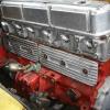
Jump to content


CHARGING SYSTEM


  • Please log in to reply
14 replies to this topic

#1 _82911_

_82911_
  • Guests

Posted 23 March 2006 - 05:23 PM

Help pplz.....
XU-1 Torry
55amp alt
Odessey battery.
Battery Isolator switch
Battery mounted on passenger side front floor.
Charge wire from alt to battery is isolated unless current is flowing through battery isolator switch.This is done with a 60amp relay.

*At fast idle (above 1800rpm) showing 13.5v @alt and 13v @battery.
*Increase in idle does not change either value.
*amp gauge is showing a charge rate of 30 amps.This is running the ignition circuit a s well as 2 holley blues.
* Turn on thermo fan and amp rate increases to 40amps.BUT the voltage now drops to 12.8 @ the battery and 13.3 @the alt.
*After 5-10 mins running the amp rate will drop slightly but the Voltage never climbs back over 12.8@ battery unless you turn the thermo back off.
My Question.....
Firstly..... can anyone see a problem here??? cause I think the Volts are a little low and the charge rate seems excesive???
Secondly......Is there much of a problem with the loss of .5 Volts from the alt to the battery??
Thirdly....is the output of the alt OK @13.5 volts??? They are supposed to be between 13.8 and 14.2 volts aren't they???

HELP got a race in 2 weeks and I don't need Electrical gremlins!!!

Cheers Greg..

Edited by 82911, 23 March 2006 - 05:25 PM.


#2 _devilsadvocate_

_devilsadvocate_
  • Guests

Posted 23 March 2006 - 06:28 PM

In the normal wiring of a LJ? the alternator is not wired directly to the battery, it goes to the power terminals and then goes to the battery via the ammeter. You have changed this around? or just have put a switching relay in the existing wire from the ammeter. (I imagine it�s the latter)
Ammeter should normally sit at ~12.30 with a fully charged battery showing that a constant charging current is going from ammeter to battery. How do you have you extra accessories connected? relays from the battery, electric pumps, fan and ignition?
If connected this way, they will create a net +ve reading on the ammeter, showing how much extra current they are drawing, whereas typically any accessory is connected to the ignition switch/fuse panel doesn�t show up as a load on the ammeter and it should stay around the central position, off course you can see the size of the load when the engine is switched off and the meter goes to the left of centre with accessories on.
This is not a problem, just what you will see with accessories connected at the battery versus at the ignition/fuse terminal.
Is 30A too much just running your fuel pumps and ign? Electronic ign, ~7A, fuel pumps � how much. Normal current that flows to charged battery ~3-5A, higher of course if it is uncharged. Your electric fan is a 10A?
55A is rated output at ~3000 engine rpm, you could be getting close to your rated output.
Re your voltage drop, 0.5v is not a substantial drop in the long route that the wire from the alternator takes to get back to the battery in the LJ, though your switching relay probably isn�t helping here(what is the voltage drop across the terminals of this relay? as well as the battery isolation switch(which is in the starter lead?)(its probably okay, starting the car presents no problems?)
I assume youve done all the necessary checking of connections for integrity, earths etc, checked for tightness on ammeter.

Anyway, if you are sure your total current is within the rating and you are not getting at least 13V on the battery(12.8V should see your battery keep afloat though), then possibly something needs attention, your running an internal regulator since 55A non standard alternator? Perhaps the brushes here could be on the way out, $30 on a new reg could improve things.

Edited by devilsadvocate, 23 March 2006 - 06:42 PM.


#3 rodomo

rodomo

    To advertise here, call 13TORANA

  • Members
  • PipPipPipPipPipPipPip
  • 17,999 posts
  • Name:R - O - B Dammit!
  • Location:Way out west of Melbourne Awstraylya
  • Joined: 10-December 05

Posted 23 March 2006 - 06:32 PM

Bigger wiring between alt. and batt. will reduce voltage drop. The longer the wire the bigger the drop. Sounds like the reg. isn't doing the job or brushes aren't carring the load. Your amp draw is probably right for what you have running.

RACV MAN

Edited by rodomo, 23 March 2006 - 06:34 PM.


#4 _devilsadvocate_

_devilsadvocate_
  • Guests

Posted 24 March 2006 - 05:30 AM

Rodomo raises a good point ^. Is the wire from the alternator of sufficient gauge to cope with the extra current that the 55A alternator puts out over the standard 35A. (Typically GM would only make things as good as they needed to be) It is important to realise though that the ammeter in standard configuration(which means no accessories connected direct to battery) is not a direct measure of alternator output, it only measures the net flow of current going to starter terminal. Is the fact ammeter calibrated? or do you have an aftermarket gauge?

#5 _Torana482HP_

_Torana482HP_
  • Guests

Posted 25 March 2006 - 05:43 PM

If the wire was not big enough it would melt and probably catch fire, when you pass more current through a wire that its not rated to, the result is excessive heat and resistance build up, and yes rodomo does have a point because if the resistance builds up then you will get a voltage drop, BUT if this is happening then the wire must be very hot which you can easily check (touch the wire), i think the problem has something to do with your thermos. Ive discussed this in another post and everyone says that when they put the thermos on, their alternator isnt up to it (55A) even though the thermos only draw 10A, they say that their idle speed drops when they come on. So keep that in mind if you cant find any other problems with your alternator etc.

#6 _Torana482HP_

_Torana482HP_
  • Guests

Posted 25 March 2006 - 05:44 PM

Oh, just thought id add, thats a cool signature youve got there devil.

#7 _Hotrodder_

_Hotrodder_
  • Guests

Posted 25 March 2006 - 08:43 PM

Ive been working with everything from large industrial power batteries, motorhomes and everything right down to little one for toys for many years, so I feel I am qualified to comment on this one, and I can certainly tell you that those output volatges are way too low for an odyssey battery.
You should have approx 13.9 volts at the alternator, and 13.8 volts at the battery, and more for a standard lead-acid battery. And that applies to ANY car.
If you are getting 0.5 volts drop between the battery and alt, find the problem, thats way too much, and you do have a problem there. You'll NEVER fully charge a bettery with anything less, and a partially charged battery will sulphate very quickly, and fail at the most in-appropriate time usually in the colder months. Sulphation is the white powdery stuff that builds up on the plates, and is impossible to remove successfully.

If I installed a battery system with any more than 5% total system cable loss I could lose my license/accreditation to design and install them.
Heres a link to a page on my website from work, there may be something there that you could learn.
http://www.kcsolar.c.../batteries.html

Edited by Hotrodder, 25 March 2006 - 08:44 PM.


#8 FastEHHolden

FastEHHolden

    Steptoe

  • Members
  • PipPipPipPipPipPipPip
  • 5,114 posts
  • Location:Central Coast NSW
  • Joined: 16-November 05

Posted 25 March 2006 - 08:53 PM

I'm with hotrodder...track down the component(s) that are causing the voltage drop.

maybe a jumper lead (insulation tape on the outside of the jaws) from B+ to battery may help to see if it is the wiring or alternator.

#9 lakeside

lakeside

    Lotsa Posts!

  • Members
  • PipPipPipPipPipPip
  • 2,703 posts
  • Name:Col
  • Location:melb
  • Car:LC SBC
  • Joined: 07-November 05

Posted 25 March 2006 - 09:19 PM

I would disconnect alt. Check voltage at alt, should rise up to near 15volts as revs rise. If you are using factory wiring to fuse box, install new cable, bigger the better, from battery. Heat, old, are big killer for voltage. Can't keep adding more current and not upgrading cable, it gets hot and melts. Greg, temporary put a big piece of cable between to battery and fusebox, see if that works.

#10 antelopeslr5000

antelopeslr5000

    Forum Fixture

  • Members
  • PipPipPipPipPip
  • 1,022 posts
  • Location:Toowoomba, Queensland
  • Car:1977 LX SL/R 5000
  • Joined: 10-November 05

Posted 25 March 2006 - 11:27 PM

Hey Greg,

I'm curious to what the voltage is of your Oddessy battery when it's removed from the car (or when the positive and earth cable are disconnected from the battery, nothing connected to draw current) ???

#11 _devilsadvocate_

_devilsadvocate_
  • Guests

Posted 26 March 2006 - 12:03 PM

yes, 0.5V voltage drop is not desirable, but the way the system is setup in the gtr, I cant see you dropping it to really low values(ie 0.1V) given the length of the wire and the number of connections that are present, along with the alternator isolator switch in 82911's system.
Perhaps the system is not really suitable for the Odyssey battery as it stands. It needs more voltage at the alternator which suggests regulator problem. One obvious way to reduce the drop would be to go direct from alternator to battery, but this will not allow correct ammeter operation.
The fact that the reg in question is only putting out 13.5V at the alternator under minimum load? should see it replaced b4 anymore headscratching is done on this thread.

#12 _devilsadvocate_

_devilsadvocate_
  • Guests

Posted 26 March 2006 - 12:39 PM

Just another thought, due to the apparent connection of relayed accessories direct to the battery in this application causing a high ammeter reading, there might be increased voltage drop occuring at the actual ammeter itself due to this. These accessories might be best connected directly to the alternator wire(on the low side of the isolation switch) and hence the current flow would not go through the ammeter(yes, with the motor off it would)

Edited by devilsadvocate, 26 March 2006 - 12:41 PM.


#13 Dangerous

Dangerous

    Forum Fixture

  • Members
  • PipPipPipPipPip
  • 948 posts
  • Location:Adelaide, SA
  • Joined: 14-November 05

Posted 28 March 2006 - 04:33 PM

My advice would be to get rid of the ammeter and ammeter wiring all together, rewire the battery +ve straight to the starter motor and also to your fusebox, and make sure the battery earth cable, alternator output to battery +ve cable, and chassis earth to engine earth cable are all large cross section (many small strands), securely bolted/connected, and run a volt meter in the dash instead of the ammeter. If you use a VN alternator, you can run the output voltage sense wire to the battery too, so that the alternator will know what the battery voltage is, and regulate its output accordingly. The older alternators sensed their own voltage output, and assumed that the battery voltage was similar.

Devil's Advocate will probably differ in opinion, but it's my opinion that a voltmeter can tell you just as much info as an ammeter, as long as you know how to interpret it. It also doesn't ned large currents flowing to and from it, so it's a much safer gauge to use.

The GTR and XU-1 ammeter wiring and gauge mounting is not an efficient or safe system.

Make sure you've got bugger all voltage drop across your battery isolator switch too.

#14 _devilsadvocate_

_devilsadvocate_
  • Guests

Posted 28 March 2006 - 08:55 PM

I get the impressions the owner of the gtr(not that weve heard back on whats been invesitigated) wants to keep things original here, and provided accessories are wired up to the alternator rather than the battery and the reason for dropped output at the alternator fixed, that it can still continue to work well
i agree with the points you make ^ Dangerous, probably why ammeters got abandoned in the 1st place, voltage drops, dash fires, etc.
An ammeter wont really tell you if your running 15V on the alternator either, unless you know the batt is fully charged and the charge rate has moved ever so slightly. Though for most people the voltmeters that are fitted in current cars, they just see the needle at about a particular spot and dont really make much of it and to them the reading always looks the same.
If it was of better resolution, ie went from 11-15V full scale with many graduations, theyd end up being more valuable for general use. Digital readout probably even better. Hard wire in a cheap multimeter.....

#15 _82911_

_82911_
  • Guests

Posted 31 March 2006 - 10:46 PM

Thanks all....
Turned out to be a dodgy amp gauge...
But while i was there i upgraded the wiring to 100 amp stuff as well as bypassing the original ignition switch circuit, so the alt wire now runs to the relay and circuit breaker then on to the battery instead of through the original starter switch..
It's all good now! :spoton:
Again thanks for the input. Appreciated.

Cheers Greg..


0 user(s) are reading this topic

0 members, 0 guests, 0 anonymous users