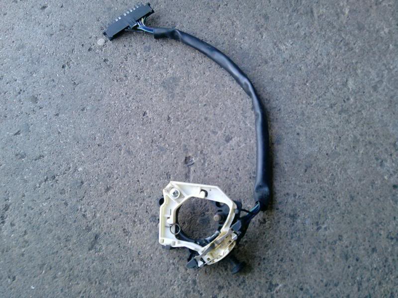
The circuit discussed in the link above has some extra requirements over the factory implementation. Looking at a VK one I have here it seems like you have everything required, you just need to add an always-on 12V feed because the hazards need to operate without the ignition on. What I have in front of me:
Black: horn
Brown: always-on 12V supply for hazard switch
Purple: ignition switched 12V supply for indicator switch(es)
Dark blue: RH indicator out
Light blue: LH indicator out
So hopefully you should be able to just connect everything as before and you will have one extra wire which needs the always-on 12V for the hazard light switch. Grab a multimeter (ohmmeter) and run the switch through the different positions to figure out what is what.
It sounds possible, though Ive never inspected one of the comm hazard switches to see how it works. It should just basically connect all four lamps to the wire coming from the existing flasher cone. If it works off the same flasher cone the switch must also isolate the flasher from its normal supply from the fuse panel, otherwise the live 12V wire connected will continue to power all the accessories when the ign is in the off position. There is no mechanism to cope with the reverse lamps as the car the switch is from has separate reverse and indicators lamps.
To overcome the non operation of the flashing lamps in reverse(the front will glow permanently too if reverse is selected), may I suggest a simple fix:
Purchase a simple bosch 30,85,86,87,87A 5 terminal relay, as on
http://www.bcae1.com/relays.htmThe idea is to use the relay to insert a break in the wire powering the reversing lamps when you select the hazards.
From the hazard switch, connect a contact that becomes live(when the switch is activated) to terminal 85 of the relay, connect 86 to ground. What needs to be examined here is that you find a contact that goes from zero to 12V and isnt in permanent contact with the indicator contacts for the switch, otherwise it wont work and will bypass reverse completely.
There are a number of ways you could do the next bit, here's one:
find the pink wire that goes from the reverse switch to the fuse panel. Disconnect it at the fuse panel and connect to terminal 30 of the relay, connect another wire to terminal 87 and run it back to the same place on the fuse panel. The idea is that contact between 30 and 87 will be broken when power is applied to the relay.
It will only cost you ~$10 and may well be worth the trouble to have the lamps work in any possible scenario.
Edited by torbirdie, 22 December 2009 - 01:28 PM.


 View Garage