Jump to content


Gemini Diff Mounting Designs


  • Please log in to reply
17 replies to this topic

#1 _Viper_

_Viper_
  • Guests

Posted 14 April 2010 - 08:05 AM

Hey guys, I need some opinions on some designs for my Gemini diff setup to present to a Engineer for approval...

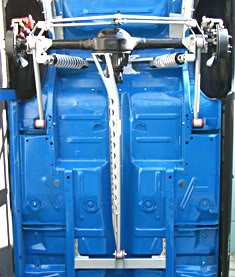
The problem with Gemini's is that standard they have a 3-link "Torque Tube" setup and when trying to convert to a diff
from another car there is very little room and no stock mounting points to fit upper control arms, Even If I was allowed
weld new mounts to the floor the upper control arms would only be about 5" long and have to remove the sway bar..

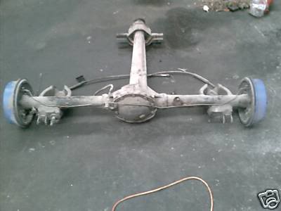
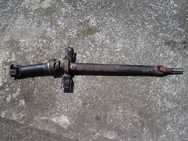
Here's a couple pics of the stock diff:
Posted Image

Posted Image

Ive come up with a couple of designs... the First is pretty much a copy of the Ford RRS 3-Link kit
Posted Image

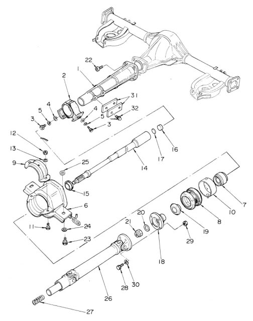
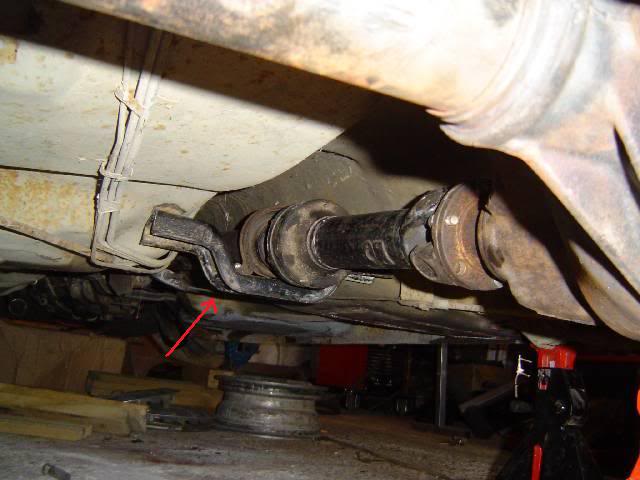
Im using a Hilux diff and the diff carrier bolts in the front the same as a 9" so im planning to use these studs to mount a center "control arm" the same as RRS do but instead of going all the way to the g/box (which isnt possible in a Gem) I will just goto the stock "torque tube" mounts (Red Arrow) and then Ill possible have to use a 2-peice tailshaft to stop the shaft hitting the Torque tube mount as the suspension is dropped (would this be required? under normal driving conditions the shaft wouldnt hit the mount, but if you jacked up the car from the body it would...)

Posted Image
Posted Image

Posted Image
Posted Image

So thats basically the first one, Id have to check if I need to used a bushed end or can use a rose joint on the end and I need to work out what sort of forces are in action in this area and how strong it has to be.

--------------------------------------------------------------------------------------------------------------

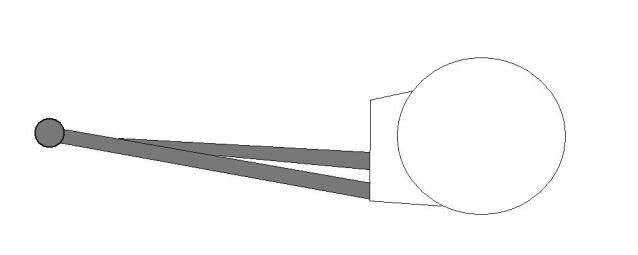
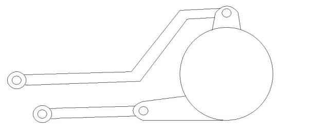
Ok Design number 2... Firstly this question will answer if this will work or not... Do upper control arms have to be striaght? or can they be bent to run down first then forward... this pic will explain better

This is side on of the diff (not the circle is the axle tube not the diff center)
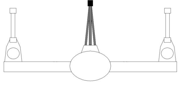
Posted Image

This is above view
Posted Image

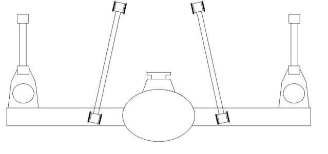
So basically a Triangulated 4-link setup but with the upper control arms bent to clear the floor of a gem.... But yea ive never seen upper arms before that wernt straight so not sure if its possible? is it just a strength thing, and bent arms would just bend more? what if I could brace them sufficiently? or is there geometry issues...


But yea opinions or suggestions would be great, I know ill still have to work out pinion angles and geometry, But im just trying to get some basic designs and a couple options to show the engineer and then we can go from there.

#2 _moot_

_moot_
  • Guests

Posted 14 April 2010 - 08:12 AM

http://www.mcdonaldb...inicontrol.html

#3 _Viper_

_Viper_
  • Guests

Posted 14 April 2010 - 08:01 PM

Engineer wont sign off on it, as its looked at as a Single ladder bar as well as requiring mounts to be welded to the floor, plus would favor cornering in one direction more then the other..

Ok for a drag car tho.

#4 ls2lxhatch

ls2lxhatch

  • Members
  • PipPipPipPipPipPipPip
  • 5,332 posts
  • Location:Perth
  • Car:LX Hatch
  • Joined: 29-May 06

Posted 14 April 2010 - 09:11 PM

The McDonald Bros setup appears to just bolt to the torque tube mount.

Posted Image

You could add a plate to both ends of the tube so it can be bolted to the factory lower arm mount as well as the torque tube mount.

Posted Image

If the engineer does not like the single arm then add another arm in the same position on the other side.

Edited by ls2lxhatch, 14 April 2010 - 09:12 PM.


#5 76lxhatch

76lxhatch

    That was easy!

  • Members
  • PipPipPipPipPipPipPip
  • 7,153 posts
  • Location:Unzud
  • Car:SS
  • Joined: 04-August 08
Garage View Garage

Posted 14 April 2010 - 09:13 PM

Engineer wont sign off on it, as its looked at as a Single ladder bar as well as requiring mounts to be welded to the floor, plus would favor cornering in one direction more then the other..


Well that eliminates your 3 link setup too then, its basically the same thing if you can only do a short centre arm. A Commodore style 4 link with panhard rod would be good (top arms can be somewhat shorter than bottom without significant adverse effects), but I don't see how you'd find anything solid to mount the top arms to.

edit: added quote for clarity since someone beat me to post

Edited by 76lxhatch, 14 April 2010 - 09:14 PM.


#6 _Viper_

_Viper_
  • Guests

Posted 15 April 2010 - 08:36 PM

Nah the Mcdonalds bro kit is welded in... Normally, it looks like they have modified it and added those mounts, Its usually welded onto the lower control arm mounts (that you can see in that pic they just havnt welded it...

And no, The Mcdonalds bro kits is offset to one side which is why its looked at as a single ladder bar and creates different handling characteristics depending on which way you turn which they dont like. My design is the same as a the RRS kit which is engineer approved, it has to be center mounted just like the Stock setup.

If the engineer does not like the single arm then add another arm in the same position on the other side.

Its also something to do with the fact the control arm is solid mounted to the top and bottom of the diff, as one side of the diff raises (going over a large bump etc) there is little allowance for the diff to rotate, and is once again worse one way more then the other... adding another arm the same would make it worse... Ladder bars are for Drag cars only... thats why my design has to be as close to the stock setup as possible for them to even think about allowing it.

A Commodore style 4 link with panhard rod would be good (top arms can be somewhat shorter than bottom without significant adverse effects

Thats pretty much what my second design is, Geminis have a panhard rod standard.... But thats why I asked the question of if the control arms have to be straight or can they be bent to clear obstacles?

Edited by Viper, 15 April 2010 - 08:49 PM.


#7 _Bomber Watson_

_Bomber Watson_
  • Guests

Posted 15 April 2010 - 09:12 PM

Ford RRS design is shit house, would frOck with your pinion angles royally.

Center arm is way to long.

Cheers.

#8 76lxhatch

76lxhatch

    That was easy!

  • Members
  • PipPipPipPipPipPipPip
  • 7,153 posts
  • Location:Unzud
  • Car:SS
  • Joined: 04-August 08
Garage View Garage

Posted 16 April 2010 - 07:21 AM

Its also something to do with the fact the control arm is solid mounted to the top and bottom of the diff, as one side of the diff raises (going over a large bump etc) there is little allowance for the diff to rotate, and is once again worse one way more then the other... adding another arm the same would make it worse... Ladder bars are for Drag cars only... thats why my design has to be as close to the stock setup as possible for them to even think about allowing it.

Your short 3 link will act in exactly the same way (Bomber's comment appears to be backwards, the longer arm is desirable to minimise the pinion angle change). The original torque tube does this too but you want to be chasing better options. Twin ladder bars has to be better than the short 3 link with regards to sideways load as it gives the same up and down movement but less roll.

Thats pretty much what my second design is, Geminis have a panhard rod standard.... But thats why I asked the question of if the control arms have to be straight or can they be bent to clear obstacles?

No reason why they can't be bent that I know of, but they may end up too large with the bracing required to actually fit. Unfortunately the length and mounting point is a long way from ideal - you effectively have the top arms significantly longer than the bottom which reverses the normal pinion angle change and you're concentrating all the leverage on a small portion of the floor pan which will require a fair bit of strengthening. But with the front mounting points so close together you're getting back to the ladder bar design anyway... :dontknow:

If the McDonald Bros kit mounts at the same place that the torque tube did then you're keeping the factory geometry (two bars may be better than one as above). If you want to go four link then you're going to need new mounts for the top arms somehow. Please note I'm not an engineer.

#9 _Viper_

_Viper_
  • Guests

Posted 16 April 2010 - 07:52 AM

Can anyone explain what the differences are between a Ladder bar and a 4-link?

If I went with the second design Im pretty sure I could get both the upper and lower arms equal length, which is the most desirable right?

Im going to be fitting the diff to the car (with the lower arms, springs, shocks, panhard rod) and get the pinion pointing in the right direction then ill have a better idea of what will fit.

But yea I agree a Longer arm like the RRS kit is much more desirable as the forward and back movement is less as it moves through its arc. But in saying that my 1st design is the same length as the stock torque tube so it would be no worse then standard

Edited by Viper, 16 April 2010 - 07:53 AM.


#10 76lxhatch

76lxhatch

    That was easy!

  • Members
  • PipPipPipPipPipPipPip
  • 7,153 posts
  • Location:Unzud
  • Car:SS
  • Joined: 04-August 08
Garage View Garage

Posted 16 April 2010 - 04:26 PM

Yes equal length arms are desirable assuming you want the pinion angle to stay consistent.

The ladder bars act exactly like the centre arm in the 3 link, they roll the diff as it moves up and down rather than attempting to keep it level like a 4 link.

But in saying that my 1st design is the same length as the stock torque tube so it would be no worse then standard

Correct, and effectively the McDonald Bros kit is the same except with a little offset but much more integrity.

#11 _Bomber Watson_

_Bomber Watson_
  • Guests

Posted 16 April 2010 - 06:33 PM

The way im looking at that RRS kit its mounted to the diff solidly like a ladder bar not pivoted?

If so then it will screw the pinion angles...

If it is pivoted at the diff end then ignore my comment.

As do ladder bars.

Cheers.

#12 _Viper_

_Viper_
  • Guests

Posted 16 April 2010 - 07:58 PM

Ok so looks like ill be trying to get the second design working in preference then, But yea the stock gemini setup is the same, so if its center mounted the same I cant see how an engineer can knock it back... But I would prefer a 4-link

#13 _Bomber Watson_

_Bomber Watson_
  • Guests

Posted 16 April 2010 - 08:27 PM

The only disadvantage i can see with your second set up is how much lower the mounts are on the body to where they are on the diff, now i dont know much about this stuff but i would be checking roll centers etc when you get it all dummied up.

Cant see any other drama though.

Cheers.

#14 76lxhatch

76lxhatch

    That was easy!

  • Members
  • PipPipPipPipPipPipPip
  • 7,153 posts
  • Location:Unzud
  • Car:SS
  • Joined: 04-August 08
Garage View Garage

Posted 16 April 2010 - 10:14 PM

The way im looking at that RRS kit its mounted to the diff solidly like a ladder bar not pivoted?

If so then it will screw the pinion angles...

That's right, hence why a longer arm is better - less change in angle due to the bigger arc.

With the 4 link, visualise (or plot) the arcs of the top and bottom arms and how they intersect and affect the pinion angle. Roll centre is an interesting one, still trying to wrap my head around that but I think that the panhard rod is going to largely control it if the arms are parallel, triangulating them would cause unnecessary hassles in this area.

#15 _Bomber Watson_

_Bomber Watson_
  • Guests

Posted 17 April 2010 - 12:19 PM

True re the roll center.

Yes your right a longer arm is better with a ladder bar, but if your designing a system from scratch its not the way i would go due to the changing pinion angle....I get what you mean now with me being backwards, i knew what i ment haha...

A simple pivot on the diff end as well would fix all problems

Cheers.

Edited by Bomber Watson, 17 April 2010 - 12:20 PM.


#16 ls2lxhatch

ls2lxhatch

  • Members
  • PipPipPipPipPipPipPip
  • 5,332 posts
  • Location:Perth
  • Car:LX Hatch
  • Joined: 29-May 06

Posted 17 April 2010 - 12:31 PM

The factory LX suspension has a significant affect on pinion angle during suspension travel. Lowering an LX can be enough to cause vibration problems.

#17 76lxhatch

76lxhatch

    That was easy!

  • Members
  • PipPipPipPipPipPipPip
  • 7,153 posts
  • Location:Unzud
  • Car:SS
  • Joined: 04-August 08
Garage View Garage

Posted 17 April 2010 - 09:13 PM

^ Yeah tell me about it :cry:

Aim for the ideal setup then come back to the real world and see what compromises have to be made... :huh:

#18 _Viper_

_Viper_
  • Guests

Posted 18 April 2010 - 12:52 PM

Hey, Well I got the hilux diff in place, the first design is definitely possible and altho not ideal would be no worse then the stock Gemini setup..

But in the interest in improving things, altho a little more complicated I believe I can get a Parallel 4-link setup to work also. With bent arms running at a diagonal from the top of the diff down and then parallel to the floor to the stock Torque tube mounts locations (where I would have a custom cross member incorporating a tailshaft loop, Only problem atm is that the upper arms will be about 200mm longer then the lower arms so not 100% ideal...

I think the next step is to talk to an engineer and see what direction he thinks is the best to head, then it will be a matter of working out what forces are involved and how strong the arms need to be as well the best location for pivot points.

Edited by Viper, 18 April 2010 - 12:55 PM.


0 user(s) are reading this topic

0 members, 0 guests, 0 anonymous users