Jump to content


Mechanical injection stupid questions....


  • Please log in to reply
15 replies to this topic

#1 _Bomber Watson_

_Bomber Watson_
  • Guests

Posted 12 February 2012 - 06:46 PM

Here we go.......Lets play confuse the frOck out of Bomber.

I picked up this MFI setup off ebay ages ago, cause it was there. I have finally decided to have a bit of a look at it, as i have an engine here i wouldnt mind using it on, mostly for shits and giggles/learning curve.

Now, the main issue is its a bit of a peculiar setup. Firstly im hoping that after reading this (soon to be long winded) post someone might be able to work out wtf brand it actually is. Also im going to say what i think all the stuff does so hopefully someone who knows more than me can correct me when im wrong.

The second issue is it was all polished at some stage, the particularly annoying part of this is the pump was polished and the pn was polished off it. All i can see on it is a bit of what appears to be an 0. Not overly usefull.

Posted Image
Posted Image
Posted Image

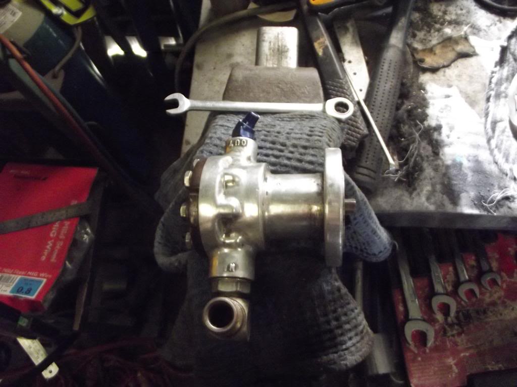
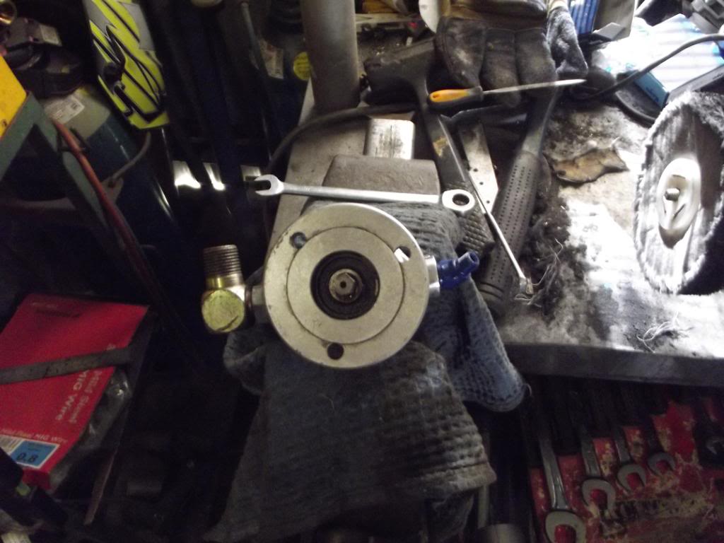
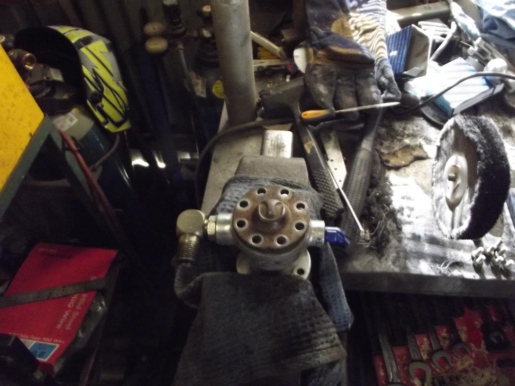
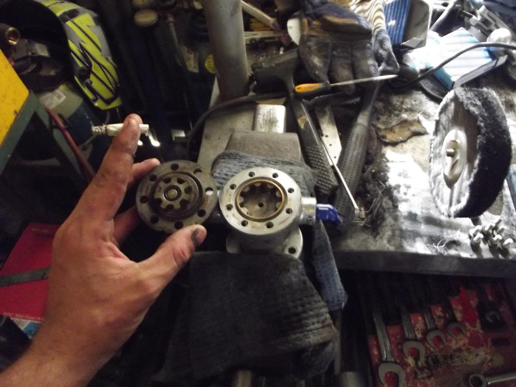
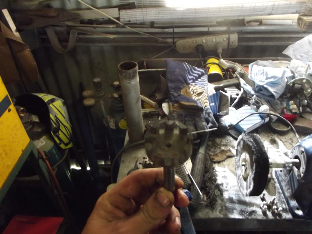
I did a bit of a naughty and pulled it apart, mostly to see if the impeller had a number on it (like hillbornes 00,0,1,2 grading system or similar) but couldn't find one. While i was in there i had a good look, to my untrained eye it appears to be in rather good nick. Very tight tolerances, no scuff marks, etc.

Posted Image
Posted Image
Posted Image

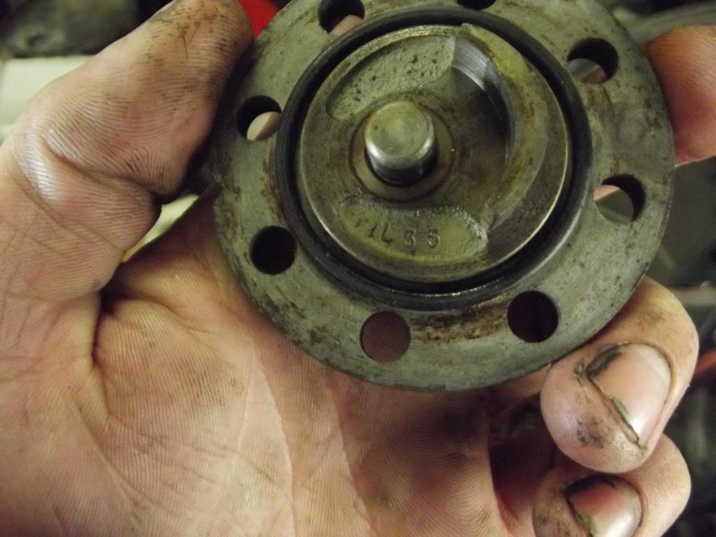
The only identifying marks of any kind i could find on the pump was the code "IL35" stamped underneath the end plate.

Posted Image

The other thing i found peculiar about the pump is that it doesnt have a built in bypass (that you run your pillbox off) on the pump like most of the common brands do. But i'll get to that shortly.

I also jerry riged a half baked test setup with a bit of line going into a fuel container and spun it with a power drill. frOck me swinging does it move some fuel. Part of the reason for doing this was to try to work out how much it pushes per revolution, i had the great idea of spinning it with a shifter, counting the turns required to move 500mls of fuel into a graduated container, but couldnt spin it fast enough to actually get it to work. If i had an optical tachometer i could work it out easily with my power drill, so i may have to beg borrow or steal one.

Now, onto the throttle body.

Posted Image
Posted Image
Posted Image

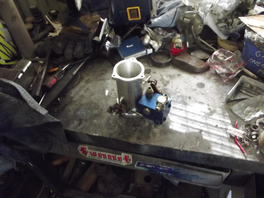
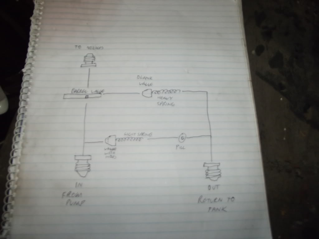
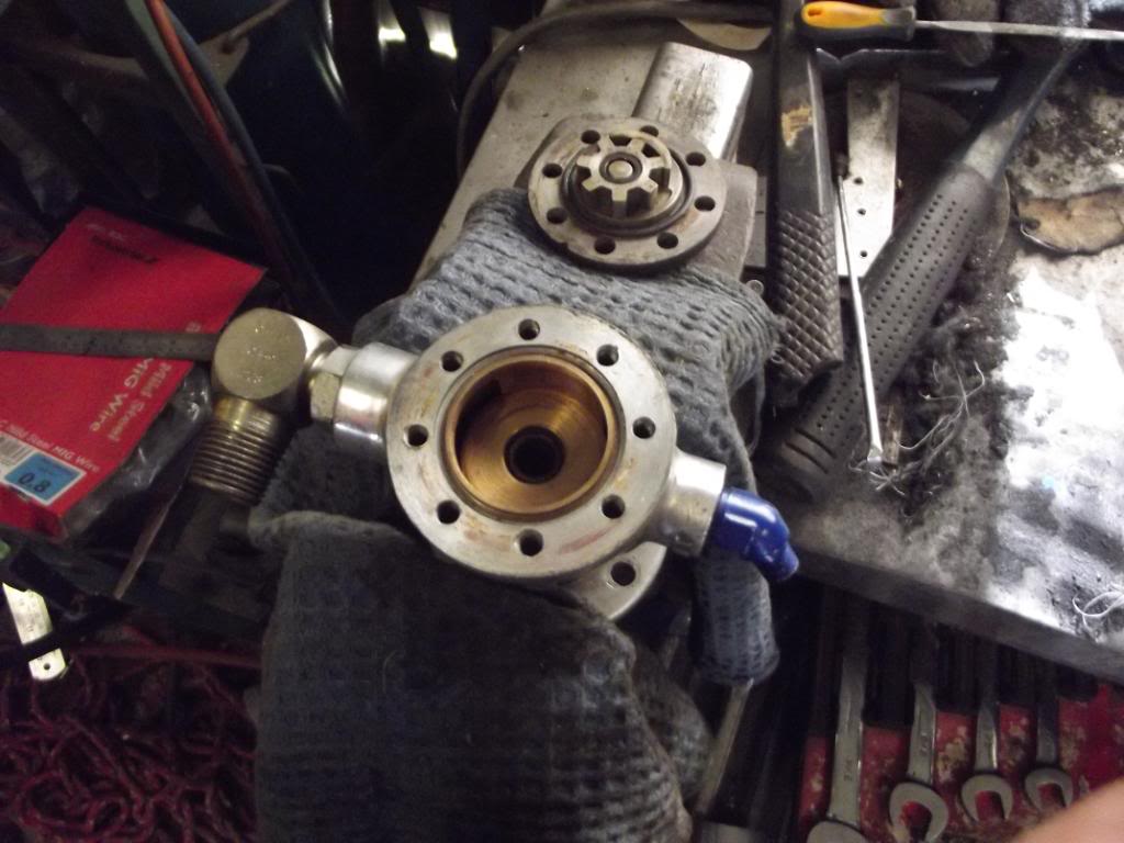
Now, apart from being rather sexy, it just seems to me to be a 2 1/4" throttle body with a pillbox/barel valve setup all in one nice neat little unit.

took me a fair while looking at it to work out how it worked, but it seems with this setup you dont need to run the pill in a return line directly from the pump like a lot of other setups.

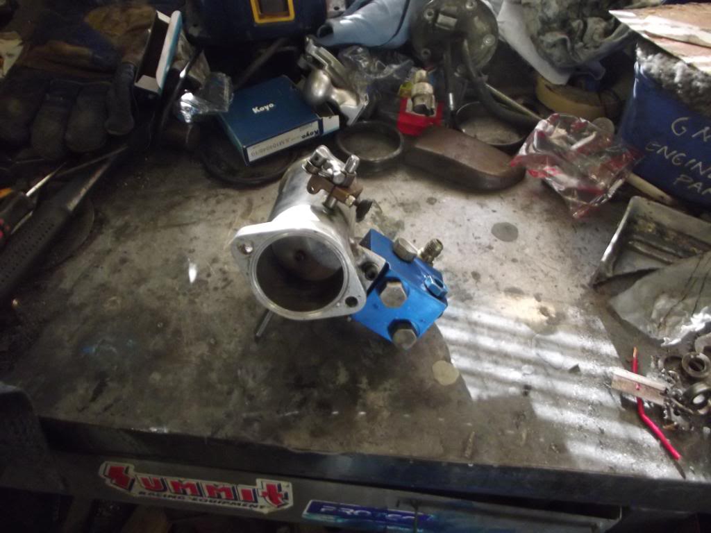
It has a Pill cover, and a cover marked with 3
Posted Image

And two more covers marked 1 and 2. 1 is in the lower left in that pick.

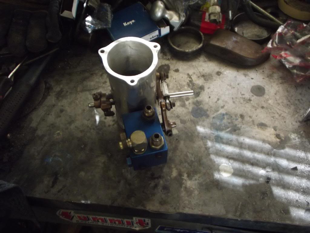
It also has three fittings coming out of it, One marked "in", one marked "out", and one unmarked. The one marked "in" is obvoiusly the fuel feed from the pump. The one makred "out" appears to be the return from the fuel tank after the pill. The unmarked one appears to be the feed to the nozzles.

Under the covers 1 and 2 are a spring and a little valve. The valve under 1 has holes in it, the valve under 2 doesnt.

Posted Image

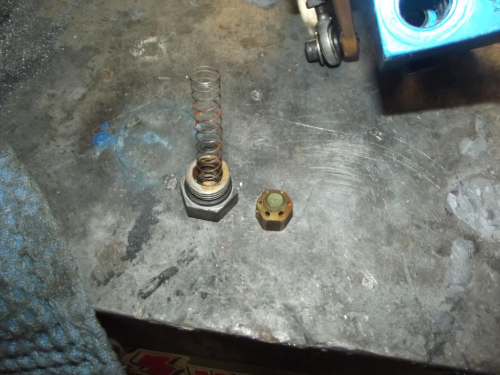
Thats the one in 1. The one in 2 looks the same but without the holes, and it has a stiffer spring.

It also has a rather peculiar looking barrell valve.

Posted Image
Posted Image

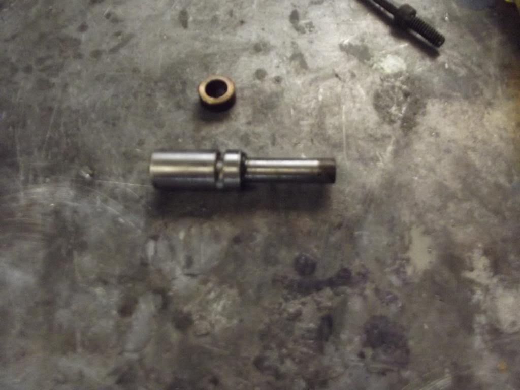
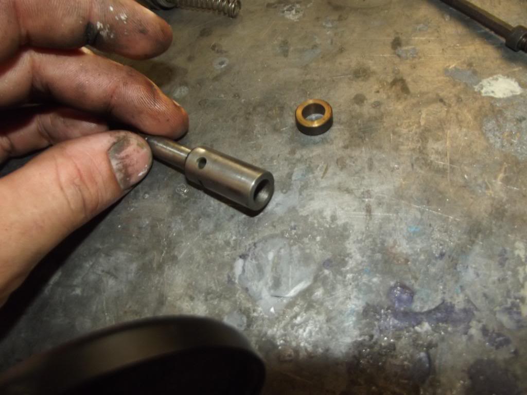
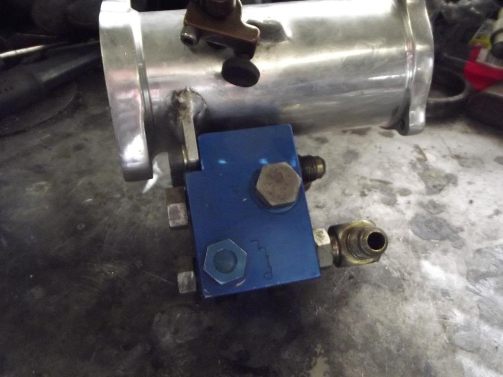
The notch is inline with the main fuel feed, obviously the further around it rotates the more fuel it allows past. The hole in the side that goes to the end is in the main fuel feed when the barrel valve is in the idle position, im guessing its a slow speed bypass of some description.

The cap marked 3 holds a spring that goes against the barrel valve, im guessing its just to keep it in place.

From what i can see valve 1 is in there as a bit of a restriction between barrel vavle and the pill. The valve 2 is in the port that the hole in the barrel vavle (the one i believe is a low speed fuel bypass) and runs to a port past the pill, into the return.

So, wtf do i have here? I have some other gear laying around, two nozzles, eight nozzle lines, some othe rrandom lines, a lot of crap that i probably wont use tbh.

Cheers.

#2 _Sandman_

_Sandman_
  • Guests

Posted 13 February 2012 - 09:23 PM

The pump looks like and Enderle. I'm guessing if you can see an O, then it's probably an 80A O pump. These are smaller than an 80A, but should be fine for 6 cyl or small V8. I think they flow around 6.5 - 7 Gal/min.
Not sure what the barrel valve is. I remember pulling a McGee one apart and it was similar, with the poppets in the barrel valve and not in the lines like enderle or hillborn.
If you feel the 2 springs, I'd guess the lighter one goes in with the barrel to hold it in place and the heavier one goes behind the poppet to maintain fuel pressure at an idle.
The lines should be easy enough to figure if you check whats flowing where. 1 line from the pump, 1 return line to tank, other line to distribution block and nozzles.
The slot in the barrel valve is to set the idle. You can get close with a leakdown tester, about 25 - 30 % with butterfly closed should get it started.
I presume your gonna run methanol through this. It's near impossible to get this style of mechanical injection running properly on petrol.
If you knew it had all been together and running successfully on an engine, you might be right, but other than that, you might spend a lot of time and effort beating your head on the wall.

Best bet is to pack it all up in a box and sent it to Someone with a injection flow bench so the pump can be flowed and everything can be matched.
I used Allan Farrer in Bris, Ph 0408734830.

I got him to do my last set, 8 hat nozzles, 2 in the blower and 8 port nozzles, plus flowed pump for engine and another for spare. Came back ready to run. Great job and really good prices.Nice guy to deal with as well.

#3 _Bomber Watson_

_Bomber Watson_
  • Guests

Posted 14 February 2012 - 08:09 PM

Cool, cheers.

You may have had me mistaken on one point. There is actually three springs in total in the little blue box of magic. One light one that goes against the barrel vavle in port #3. Then one heavy spring that sits against a solid poppet valve in port #2, which is in line with the back side of the barrel valve and in line with what i belive to be the low speed bypass (and you didnt correct me so i assuem thats correct) and heads to the return side of the pill, hence bypassing it, and one light spring on the little valve in port #1 which is between the inlet and the pill.

Sorry if thats not totally clear im still very very new to this shit haha.

Now, some basic calks, working on the high side the combo i wish to try this on will probably make around 300hp max. Just a basic blow through turbo'd 202. Not sure if your familiar with the battle of the hand grenades project that got quiet some attention about 18 months ago, but its the engine from that. Currently running a 500 holley on petrol, but i wish to convert it to meth and use this injection system.

According to the magnum performance website you need about 1lb per hour per hp on methanol. That works out to about .75gpm for 300hp. Is that right?? Sounds a bit low.

Please keep in mind this is just a practice engine that i dont care if i blow up!!

Now i have seen a lot of blow through turbo MFI setups, most of them run the regular pill tuned to WOT at 0psi boost, and then have a rising rate "pill" feeding a second set of injectors that comes on as boost comes on giving a form of controlled fuel curve.

Im thinking that seeing though im running relatively low boost with this setup i'd get away with just tuning the mfi setup to WOT with full boost, it will simply be rahter fat whilst it spools up, correct?? Spool up time is less than half a second. This in my mind may also act as a form of antilag.........

Thoughts??

Cheers.

#4 _oldjohnno_

_oldjohnno_
  • Guests

Posted 14 February 2012 - 09:12 PM

This is outside my experience so the sensible thing to do would be to ignore everything below. But it sounds like fun so I'm gonna weigh in anyway...

For me at least, it's much easier to visualise the functioning of a circuit like this by sketching out a circuit diagram, like a hydraulic schematic. It's basically a hydraulic design project anyway, and there is nothing that you want to do that is impossible. Sketching the circuit and posting it here will also help others to visualise what you have.

I wouldn't even think about doing the initial setup on a running engine, even a junk one. Setting up from scratch on a running engine would a good way to cook a lot of pistons and burn a lot of fuel I think. I'd be inclined to set up some sort of variable speed drive for the pump (even if it's just an old "mule" engine) and use shop air with a regulator to set up your boost-actuated controls. I think this would be much easier and cheaper than on the engine, and you'd have some chance of it actually working when it did get fitted.

The idea of using separate nozzles for boost conditions sounds reasonable, at least it'd let you run smaller main nozzles that wouldn't drool so much at light throttle.

I think setting it up for boost conditions even when unboosted will make it more than just a little fat, and that it may have the opposite effect to anti-lag.

But really you should be talking to people that have done this stuff for years.

Oh yeah, one more thing, CLEAN UP YOUR frOckIN BENCH! ^_^

Edited by oldjohnno, 14 February 2012 - 09:16 PM.


#5 _Bomber Watson_

_Bomber Watson_
  • Guests

Posted 14 February 2012 - 09:55 PM

Ah, yeah, theres an epic shed clean up kinda happening atm, the bench is on the list of things to tidy up.

As they say, active mind messy work area, you should see my bedroom!!!

Now, your lucky im not overly sensible, so i bothered to read and absorb your thoughts (always welcome....)

I'll see about drawing up a diagram tomorow arv when i get home from work and im less drunk.

On the note of the fuel settings with one system for boost conditions being overly fat off boost, your probably right. Come to think of it 15psi THEORETICALLY will make about twice the hp and require about twice the fuel, so that half second between nailing it and actually being on boost will be awesomely rich.....

And looking at antilag more it seems they only richen it up to cool the thing down a bit, the main function is retarding the timing, a lot, up to 40 degrees after, to promote combustion in the exh manifold, so your probably right.

I agree the thought of running more smaller nozzles sounds good everywhere, i was just trying to get away with buying less nozzles......There not cheap....Unless im manly and make some out of gal fittings found in the bucket under the bench.

Now, your test bench idea, how would i go about setting this up easily and quickly and half drunk?? I get what you mean but just wondering how i would go about getting any form of meaningfull results from it, unless i suppose i just measure the fuel outflow from the fitting to the nozzles over time and see how close this is to my calculated requirement....I suppose i could work that out. The thought of having six little beakers with a nozzle in each sounds messy and difficult to me. 12 if i go the two injector per cylinder route....

Cheers.

#6 _Sandman_

_Sandman_
  • Guests

Posted 14 February 2012 - 10:41 PM

Sorry. Didn't read it right about the other check valve. I'd assume it's a secondary bypass. It should dump fuel when you back off the throttle. Basic drag race systems don't use them, as your only full throttle or stopping.
Speedway, boats etc need it though. When you set the scroll on the barrel valve for your idle, the pump will only be putting out a few lbs of pressure(depending what the check valve spring is set at. But at full throttle, you'll have 100+lbs of pressure. So, if your at full throttle, then shut it for a corner or whatever, the barrel valve comes back to where you set the idle at, but instead of say 10lbs fuel pres, you'll have 100+, because the engine/pump rpm doesn't drop instantly. Therefore you end up with a bunch more fuel going through the same restriction that you set it to idle with. If this happens, when you get back on the throttle, the engine is loaded up with fuel and will stumble before clearing itself. Sec bypass dumps this extra fuel pres back to tank.

On V8 set of injector, I set the butterfly at .004", then 25% leakdown on the bbl valve. (On a single butterfly setup, you may need more than .004", try .006" & 25%) That will start and idle ok. If you blip the throttle and it pops back, then it's too lean. Richen bbl v/v.
If you not running much boost, it should be OK to just run a primary set of nozzles. You can set the idle rich, it won't worry it at all. In fact, it needs to be richer than you probably think, as injectors don't have an accelarator pump for when you snap the throttle open, so having excess fuel helps cover any flat spot or backfires. If you haven't played with alky before, you will be surprised how much you can put in an engine without flooding it. Unlike petrol.
If it's blowing a bit of black (fuel) smoke and idling a bit rough, don't worry.

When you put your pump back together, the qtr moon has to be in the right place, otherwise it will suck instead of pumping. It goes in one position for belt drive, and 180* around for cam drive.

How many nozzles are you planning on running?

How many nozzles came with it? And What sizes?

What size pill was in it?


(Yeh, ur bench is a bigger mess than mine)

#7 _oldjohnno_

_oldjohnno_
  • Guests

Posted 15 February 2012 - 06:27 AM

For the test bench you'd need some way of running the pump at a range of speeds similar to what it would run on the engine. Lathe perhaps? And I wouldn't worry about trying to measure the flow from each nozzle individually, the whole lot could dump into one big container. It shouldn't be too hard to work out roughly the volume you'll need under various speeds/loads, it's just a matter of making it happen. Do you have a drive for it to suit the little six? I know Brett at Sonic Injection has made some modified timing covers to suit these pumps.

My bench is in a similar state at the moment...

#8 warrenm

warrenm

    Forum Fixture

  • Members
  • PipPipPipPipPip
  • 2,124 posts
  • Location:Central West NSW
  • Car:1972 LJ Torana
  • Joined: 08-November 05
Garage View Garage

Posted 15 February 2012 - 07:14 AM

Aren't all benchs a big shelf for storage? :mellow:
Bomber, have you had a chat with Mark Stewart? He's been playing with these things for a little while.

Edited by warrenm, 15 February 2012 - 07:19 AM.


#9 orangeLJ

orangeLJ

    Yes, yes I do post alot!

  • Members
  • PipPipPipPipPipPipPip
  • 10,261 posts
  • Joined: 02-May 06

Posted 15 February 2012 - 12:16 PM

Mechanical injection is nowheres-ville to me, buuuuut

I think you would have a fair bit of trouble setting up antilag on something running basic elec ignition and mechanical injection, there are aftermarket antilag controllers but its a Daisy Chain to get right and even when you do, its pretty terrible for the valvetrain, turbo and manifold :)

#10 _Bomber Watson_

_Bomber Watson_
  • Guests

Posted 15 February 2012 - 07:20 PM

As per my hero's request, one very dodgily drawn diagram

Posted Image

i omitted the light spring that sits against the barrel valve, as i already know what that does. Thats just a circuit diagram.

Now, sandman, you say the secondary bypass isnt generally used in drag racing, i assume with a manual (which this vehicle will have at first) it would also be required?

Lookin at the pump i figured the half moon thing had a similar function to that. The way i have it atm it pumps when spun anti clockwise, so im guessing thats for cam drive use??

How many nozzles, still up in the air. Either six or 12. Or perhaps six primary ones and one or two big ass secondary ones feeding into the tb or just below it for the boost enrichment might work??

Currently have two nozzles, and cant really see any identifying marks on them. The holes look big though.

Pill is a 115. Im also going to assume thats useless.

Johnno, probably going to just belt drive the pump. I would prefer to not deal with Brett as im not entirely over his little endeavor to prove he's a wanker from a while ago.

Re the bench, my current thoughts are an optical tachometer and a power drill to run it....Sound good?? Hehehehe.

Warren, was about to call Mark and get him to have a look at this thread before i started getting some usefull replies. Im pretty good at the moment but yes, he's high on my list of people to ask. Bit hard to explain all this stuff over the phone picks are way betterer.

Chris, take your computer controlled billet ideas elsewhere :P

Now, next question, i've decided i can make nozzles instead of buying them. Is this true or am i an idiot??

Cheers.

#11 _oldjohnno_

_oldjohnno_
  • Guests

Posted 15 February 2012 - 08:46 PM

Lets just assume for the sake of simple sums that you're going to run around 15 psi boost with two sets of nozzles. So that the flow through the auxilliary nozzles at full boost would be roughly equal to the flow through the main nozzles.
You could control the auxilliaries fairly simply (in theory, anyway) by using two equally sized pills in parallel. One would be connected the normal way, the other via a 3 port valve. The P port would be the inlet and tee into the pump pressure line, the A port to the pill and the B port to the auxilliary nozzles. Boost pressure would shift the spool against spring pressure thus gradually shifting the flow from A to B. It would take some tuning of course but you can do a lot with spring pressures and a bit of spool geometry. If this doesn't make any sense I could draw it if you're interested. For different boost levels you'd obviously have to use different area ratios between the two pills.

As for nozzles I don't think making them would be a problem, but getting equal flow from each may be. But depending on the location this mightn't be a problem. I've heard of people making streetable systems using Bosch K-jetronic mechanical injectors. These have the advantage of being able to maintain a reasonable spray over a much wider range of flows than the Hilborn/Enderle style nozzles. Whether you'd be able to find any big enough for alky might be a problem though.

#12 _Bomber Watson_

_Bomber Watson_
  • Guests

Posted 15 February 2012 - 09:34 PM

Hmmm K jetronic nozzles should be easy enough to find. Local wrecker here has heaps of 80's volvo's....

Im guessing you know a little bit more about hydraulics than i do, but im not entirely sure your idea would work??

With a Pill attatched to port A and the aux nozzles to port B, as the valve switches from port A to B wouldnt that just take it from metering the fuel back to the tank to supplying full unmetered pump pressure to the nozzles??

Or am i really confused??

Cheers.

#13 _Sandman_

_Sandman_
  • Guests

Posted 15 February 2012 - 10:00 PM

The way you have it drawn should be right.
I should have been a bit clearer about the secondary. It's not nessessary in drag racing. They still get used, but doesn't make your car any quicker. I've had a set with sec bypass then changed to without, never made an ounce of difference. But as you have it, you might as well run it.
What head/port arrangement have you got? 12 port or 9 port. If it's 12 port, then go for 1 injector in each runner, and your idea about a couple upstream of turbo would work. As well as enrichment, it would cool the intake air considerably.
I'm not sure what the best arrangement would be for port nozzles on a 9 port head, whether to run 2 in each runner aimed at the respective ports, or 1 larger one in each runner, spraying toward the 2 intake valves. I guess if you set the nozzle a little further away from the head, the fuel would go to the right port.
As far as making nozzles, without knowing you expertise and equipment you have, you could make them, but they're not too expensive, so if you buy a set, you'lll know they're pretty right.
Nozzle holders like the pic would be good in the manifold, and before the turbo, as they spray the fuel in a kinda fan pattern. Once you have the holders, then you buy what size jet you need to go in them.
Posted Image

#14 _Bomber Watson_

_Bomber Watson_
  • Guests

Posted 15 February 2012 - 10:15 PM

Well there ya go, i always thought the bit you pictured was the nozzle, but i just pulled mine apart again and the little alloy slip thing inside it seems to be the nozzle. Marked 42.

By one or two big nozzles for the boost enrichment, I ment in the tb, not upstream of the turbo. I intended to blow through the turbo. But i suppose it wouldnt really matter a fark.

Running a 12 port. Currently tossing up whether to put the tb on a factory carb manifold, or whether to use a vk efi manifold. Thats also probabaly pretty irrelevant for this discussion though.

Cheers.

#15 _Sandman_

_Sandman_
  • Guests

Posted 15 February 2012 - 10:58 PM

Use whichever manifold flows the best.
The nozzle holder picured is an enderle one. Nozzle screws into it.
If you put the enrichment nozzles upstream of the turbo, the methanol will atomise going through the turbo, and chill it all down. Have you watched the drags and seen the ice forming on injector hats?

#16 _oldjohnno_

_oldjohnno_
  • Guests

Posted 16 February 2012 - 05:58 AM

With a Pill attatched to port A and the aux nozzles to port B, as the valve switches from port A to B wouldnt that just take it from metering the fuel back to the tank to supplying full unmetered pump pressure to the nozzles??


Cheers.


No, the idea of using two pills is to maintain a constant pressure for a given pump speed regardless of whether one or both sets of nozzles are in use.

Thinking about K jetronics and wreckers, perhaps the Bosch metering head could be converted to use as the boost enrichment controller? You could remove the air flap and replace it with a pressure actuated diaphragm.


1 user(s) are reading this topic

0 members, 1 guests, 0 anonymous users