Jump to content


Photo
- - - - -

SS Hatch


  • Please log in to reply
589 replies to this topic

#351 myss427

myss427

    Forum Fixture

  • Members
  • PipPipPipPipPip
  • 1,636 posts
  • Location:Canberra
  • Car:427 hatch, CV8 Monaro, Ve SSV ute. Was part owner A9X sedan until he sold it without telling me!
  • Joined: 17-November 05
Garage View Garage

Posted 28 July 2016 - 03:35 PM

Some of our rules regarding vehicle requirements apply to the date of manufacture, others to the date of first registration in this country. Because this car was imported and first registered here at a later date, that means it legally requires a high stop light and won't pass an inspection without one.


The standard style window mounted lights are huge and really obstruct vision out the back. The one that came with the car departed quickly, replaced by a 'slim' LED one, but still quite large on the window and annoyed me. I finally got around to plan B, made a small housing flush mounted in the spoiler with a bright red LED strip inside it (its completely white/clear when not going).


20160727_171213.jpg


Also made a spring-loaded contact for the power supply at the left hand rear corner, uses the same spot as the compartment light switch on the right side but instead of earthing it has an insulated power wire pass through it to a contact on the lid. No more wires hanging out.


That's kind of funny, that in the same country you can register a full chassis blown big block hatch that looks like a race car, and they ping you for a high mount stop light?


#352 76lxhatch

76lxhatch

    That was easy!

  • Members
  • PipPipPipPipPipPipPip
  • 7,153 posts
  • Location:Unzud
  • Car:SS
  • Joined: 04-August 08
Garage View Garage

Posted 29 July 2016 - 04:06 PM

Yeah the rules here aren't as open as some people like to make out


#353 76lxhatch

76lxhatch

    That was easy!

  • Members
  • PipPipPipPipPipPipPip
  • 7,153 posts
  • Location:Unzud
  • Car:SS
  • Joined: 04-August 08
Garage View Garage

Posted 06 September 2016 - 09:01 AM

Installed a dual flow adjustable PCV valve, allows the idle flow to be reduced compared to normal cruising and offers adjustment for different manifold vacuum. Very pricey but it works well. Before I had to have idle spark advance at 16 degrees and the throttle almost completely closed (even then it would idle slightly fast when quite hot when the IAC would close completely). Installing this allowed me to add 4 degrees of timing and crack the throttle slightly, with a few IAC steps to spare (I think/hope).

20160906_104257.jpg

Edited by 76lxhatch, 21 July 2017 - 11:52 PM.


#354 76lxhatch

76lxhatch

    That was easy!

  • Members
  • PipPipPipPipPipPipPip
  • 7,153 posts
  • Location:Unzud
  • Car:SS
  • Joined: 04-August 08
Garage View Garage

Posted 09 May 2017 - 01:37 PM

Made an SS horn cap to replace the Momo one
20160408_120557.jpg

Got all the major stuff re-certified, about the only change was an extra bracket on the steering rack mount. They generally like them to be mounted in double shear even though the factory didn't do it, this gave an extra redundancy in lieu of that. Before welding, the piece on top is now welded to the mounting adapter and the piece underneath to the cross member to provide a decent chunk for threading into.
20170204_140745.jpg

When I did the EFI conversion I put a tap on the heater hoses under the bonnet, especially with the new core there is too much heat soak otherwise and the standard air flap can't control that. Finally got around to actually hooking the tap up to the controls though, it just piggy-backs onto the air flap cable.
20170423_131202.jpg
20170423_131238.jpg

Edited by 76lxhatch, 21 July 2017 - 11:53 PM.


#355 axistr

axistr

    Forum Fixture

  • Members
  • PipPipPipPipPip
  • 1,169 posts
  • Location:North west sydney
  • Joined: 19-November 05
Garage View Garage

Posted 10 May 2017 - 09:33 AM

Did the same on mine, works well and you can progressively control the amount of coolant flow through the core with the control leaver on the dash. Had the SLR out last night, nice and worm.


I am surprised they made you put an extra bracket on the rack. The toranas didn't have any issues with the original mounting points, and much stronger than most modern cars.   


#356 76lxhatch

76lxhatch

    That was easy!

  • Members
  • PipPipPipPipPipPipPip
  • 7,153 posts
  • Location:Unzud
  • Car:SS
  • Joined: 04-August 08
Garage View Garage

Posted 10 May 2017 - 03:24 PM

Yeah I probably could have argued the point but since he didn't have any concerns with my welding and it was the only tweak required for a long list of mods it was easier to just do it.

#357 _Axewound_

_Axewound_
  • Guests

Posted 10 May 2017 - 04:03 PM

I am liking the SS horn cap!

Edited by Axewound, 10 May 2017 - 04:04 PM.


#358 76lxhatch

76lxhatch

    That was easy!

  • Members
  • PipPipPipPipPipPipPip
  • 7,153 posts
  • Location:Unzud
  • Car:SS
  • Joined: 04-August 08
Garage View Garage

Posted 01 July 2017 - 08:58 AM

Images relocated, good riddance PhotoBucket.

http://img.v8comp.co.nz/Torana

20151017_125144.jpg

#359 hanra

hanra

    Oh My, Don't you post alot

  • Members
  • PipPipPipPipPipPipPip
  • 10,832 posts
  • Name:Brad
  • Location:Farrrrrr North Qld
  • Car:1975 LH SL/R 5000, 1967 Morris Cooper S, E36 BMW, Toyota Corolla, Isuzu DMax
  • Joined: 24-March 11

Posted 01 July 2017 - 09:22 AM

R.I.P to this build thread also.

#360 Heath

Heath

    I like cars.

  • Administrators
  • PipPipPipPipPipPipPip
  • 18,309 posts
  • Name:Heath
  • Location:Eastern Suburbs, Melbourne
  • Car:Heavily Modified UC Sunbird Hatchback
  • Joined: 07-November 05
Garage View Garage

Posted 01 July 2017 - 07:18 PM

PhotoBucket is such a fucking pile of shit. I don't know why they let it get so bad and never did anything about it. What a spew!

#361 76lxhatch

76lxhatch

    That was easy!

  • Members
  • PipPipPipPipPipPipPip
  • 7,153 posts
  • Location:Unzud
  • Car:SS
  • Joined: 04-August 08
Garage View Garage

Posted 03 September 2018 - 12:17 PM

Have had a new engine in the works for a while, finally found the time/energy and funds to make some progress recently. VL block with a bit of a tidy up and clearance work for 3.48” stroke crank, painted and fresh freeze plugs fitted:

20180729_165057.jpg

Machined up a new oil pump bushing and fitted with a screw-in retainer (not sure what happened to the roll pin), also threaded oil gallery holes for 3/8” NPT plugs and re-routed driver side lifter gallery feed from front cam bearing:

20180727_165524.jpg

Cam is a basic 230@50, 0.535” lift hydraulic flat tappet fitted with 0.002” under bearings. Scat crank with Holden rod journals and matching Scat 5.7” rods, ARP main studs:

20180803_173250.jpg

Probe forged pistons which I machined a small extra dish into to keep the compression around 10.2:1 with early heads (59cc chambers). Also cleaned up a few of the casting dags in the block:

20180804_125419.jpg

Made a nicer cover plate for the mechanical fuel pump hole in the timing cover:

20180825_161831.jpg

Changed flywheel to a “light weight” (not really, its slightly heavier than two different factory items I have here), “explosion proof” steel item:

20180828_124113.jpg

Cleaned up and used the existing heads and manifold with a bit of extra porting. I did notice that my PCV baffle in the rocker cover was actually doing the opposite of what its supposed to, causing too much oil to track through the baffle and into the intake. There just isn’t enough space between the end of the cover and the first rocker to improve this with the standard PCV location, so I made an adapter that fits to the top of the cover in the un-used cap location – this also acts as a mini vapour separator:

20180825_121533.jpg

Also revised the baffle under it to a version that doesn’t contact the rocker cover. Unfortunately the rocker adjusting nuts need a lot of space (hence the round holes) but should still be better:

20180825_152940.jpg

Had a minor snafu with clearance to the sump windage tray on first start, couldn’t actually tell this was touching when turning over by hand. Only took 30 seconds with a hammer to fix, on top of the several hours to remove and replace the front suspension around it (faster than removing the engine again)!

20180901_093900.jpg

No photos of it installed since it looks the same as before on the outside. Have done nearly 200km so still only just run-in but everything seems good so far.

#362 76lxhatch

76lxhatch

    That was easy!

  • Members
  • PipPipPipPipPipPipPip
  • 7,153 posts
  • Location:Unzud
  • Car:SS
  • Joined: 04-August 08
Garage View Garage

Posted 23 November 2018 - 02:09 PM

Had some minor issues with valve train noise which I tracked down to the springs not seating right, they look like they're standard diameter but they are ever so slightly larger. So heads off and machined the pockets just slightly:
20181020_132821.jpg

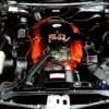
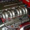
For some reason I didn't get the rear main seal right this time, so may as well pull the whole engine and re-do that (changed to rubber/neoprene seal). While we're at it the cam was a bit lackluster so drop in something a little bigger:
20181114_140249.jpg

That made a nice improvement, although I'm still working through the EFI tuning to make it drive as smoothly as possible. Tried it out on the drag strip with a best of 13.2 but inconsistent again, and running mid 13s @107mph so there's definitely more. Clutch issues again, I didn't do too much damage but the car definitely smelled a bit that day. Ordered one of these to fix it:
clutch.jpg
(still on its way)

Also decided that the diff ratio is too in-between at 3.45, it was good with the four speed but with the five speed (fifth gear is 0.64:1 so quite tall) and the new cam liking a few more revs I decided to change it back to 3.91:
20181117_120644.jpg

Of course the diff change means I need to fix the speedo again - no problem, I have a couple of spare gears. Oops, none of them are even remotely close. Thought I'd try something different and see if I can get the 3D printer to produce something that will work:
speedo_gear.jpg
20181118_192911.jpg
With a little clean up it fits and works, we'll see how long the ABS plastic lasts (I suspect they are normally nylon?)

While the engine and gearbox were out again I decided to move the shifter to the rearward position so it falls to hand better. Unfortunately that meant the four cylinder console surround no longer fits (I believe someone changed it when the Toyota 5 speed was originally fitted, now long gone - shifter position is more standard again now). Rare Spares sells the parts to change it back to original but wow they are expensive and I don't really like the look of the switch panel in particular. So I made a surround to hold the boot:
20181114_172811.jpg
and went back to a bit of CAD drawing and used the 3D printer to create a piece, along with an aluminium panel with a light coating of wrinkle black:
20181122_143615.jpg
along with painting screw heads black and continuing the red pin striping, I think it looks OK:
20181123_124903.jpg
The console needs a respray at some point to tidy things up.

An no surprises here but the clutch master cylinder is slowly bypassing (can't hold the pedal down too long, it will release by itself!) and starting to leak again due to the strange angles. Heath picked it already:

I thought a handy bloke such as yourself would have tried to remove the rocker cover and decided to do an under-dash clutch master creation instead?

So I got one of the shorty Tilton master cylinders, and will be attempting some custom bracketry to install this when the new clutch arrives (or before if the current one dies completely):
new_clutch_master.jpg
Hopefully its just short enough to mount it level to the left of the column under the dash, and the hose will run out the existing pushrod hole so I can still mount the reservoir in the engine bay where it belongs.

Edited by 76lxhatch, 23 November 2018 - 02:13 PM.


#363 Toranamat69

Toranamat69

    Forum R&D Officer

  • Members
  • PipPipPipPipPip
  • 2,117 posts
  • Location:Brisbane
  • Joined: 07-November 05

Posted 23 November 2018 - 07:28 PM

Good work. I like the 3d printed bits.

#364 axistr

axistr

    Forum Fixture

  • Members
  • PipPipPipPipPip
  • 1,169 posts
  • Location:North west sydney
  • Joined: 19-November 05
Garage View Garage

Posted 24 November 2018 - 06:12 AM

Good work as usual. I used a second hand BA falcon clutch pedal assembly off evil bay. Bolted in very easy no real mods to the car needed. Only had to put around 2inch of metal to extend the pedal length to get it to line up with the brake pedal. Very light and good feel. Inlet hose lined up with old push rod hole.

#365 76lxhatch

76lxhatch

    That was easy!

  • Members
  • PipPipPipPipPipPipPip
  • 7,153 posts
  • Location:Unzud
  • Car:SS
  • Joined: 04-August 08
Garage View Garage

Posted 24 November 2018 - 07:27 AM

Thanks guys


we'll see how long the ABS plastic lasts

Turns out about 3 days...
20181124_102022.jpg


#366 Bigfella237

Bigfella237

    Socially Distant

  • Members
  • PipPipPipPipPipPipPip
  • 4,373 posts
  • Name:Andrew
  • Location:Far South Coast of NSW
  • Car:(s) not as many as I'd like but more than I've got space for!
  • Joined: 31-October 14

Posted 24 November 2018 - 08:43 AM

Kinda surprised it lasted that long myself!


I've never tried printing with nylon, it's supposed to be heaps tougher but requires a heated enclosure if memory serves.


Beside the obvious... how accurate was the speedo with your printed gear?


#367 76lxhatch

76lxhatch

    That was easy!

  • Members
  • PipPipPipPipPipPipPip
  • 7,153 posts
  • Location:Unzud
  • Car:SS
  • Joined: 04-August 08
Garage View Garage

Posted 24 November 2018 - 08:14 PM

I reckon the gear was reasonably strong but not sure how the ABS goes with the oil and its not great with heat. Still seemed solid enough when I pulled it out again (well, what's left of it). I think the 23 tooth gear is the maximum number of teeth available in a standard gear and have seen some advertised as having limited lifetime for this reason (thinner teeth). It also probably doesn't help that my design didn't produce a perfect helical gear, was hoping that wouldn't matter for this application with low load, was worth a try anyway. My little 3D printer isn't set up for nylon but I think that's what most are made of - even the layered ABS isn't as strong as properly molded, its really only meant for prototyping after all.


Accuracy was about as good as it gets with a cable driven speedo, with 275/40/17 tyres and 3.91 diff the factory speedo was spot on.


#368 axistr

axistr

    Forum Fixture

  • Members
  • PipPipPipPipPip
  • 1,169 posts
  • Location:North west sydney
  • Joined: 19-November 05
Garage View Garage

Posted 25 November 2018 - 07:34 AM

You could use the 3D printed gear as a templet for casting and pour in aluminium to make a new gear.


#369 76lxhatch

76lxhatch

    That was easy!

  • Members
  • PipPipPipPipPipPipPip
  • 7,153 posts
  • Location:Unzud
  • Car:SS
  • Joined: 04-August 08
Garage View Garage

Posted 29 November 2018 - 12:07 PM

Aluminium is an interesting thought, although would have to double-check what the drive gear is made of as I'm not sure I'd like to have metal on metal in that location (plastic would be fine). I've ordered a proper gear anyway, looked at electronic speedo conversions but can't find anything I liked the look of, would rather have the original.


Clutch arrived:

20181129_142829.jpg

Looks to be reasonable quality, comes with ARP fasteners and no less than three different plastic alignment tools. The plate closest to the flywheel has a proper marcel spring, the other one doesn't (or is very minimal). Need to pull finger and sort out the master cylinder then get this changed over.


In the mean time I finally bought a proper alternator to resolve some low voltage issues. I had a new 120A unit but it was one of those universal ones so it didn't put out a lot at low revs. I was using an old VN 85A one for a while which was marginally better but still not great. Pulley ratio is fine (~2.45:1) and engine idle speed is now relatively high (925rpm) which gives me a good 2200rpm at the alternator at idle. However I have aftermarket injectors, two fuel pumps, twin 14" cooling fans and by the time all that is going and you turn the lights on, the ECU was showing under 12V at times!


Solution: 140A Mitsubishi style unit as fitted to LS1 Commodores. This is meant to give better output at low revs and even came with a test report - 101A output at 2000rpm. Physically fitting it requires changing the pulley (I had to make a spacer but I do have oddball pulley spacing) and changing the tensioner bracket - if I ever get around to it I might change this to a turnbuckle type thing for easier adjustment but it works for now:

20181128_194153.jpg

Wiring it up is the same as a VN unit, load and sense wires, but with a different plug or you can cheat and use spade terminals.


Speaking of wiring I thought I'd better replace the old starter, earth and alternator leads with new ones of appropriate size to make sure there are no problems in that department. Only problem is the leads come in weird colours:

20181127_103308.jpg


Fixed:

20181127_103612.jpg


Now the ECU reports an immediate 13.7V at idle, which doesn't seem to drop no matter what's running. Voltage at the battery/sense wire is a constant 14.3V.


#370 76lxhatch

76lxhatch

    That was easy!

  • Members
  • PipPipPipPipPipPipPip
  • 7,153 posts
  • Location:Unzud
  • Car:SS
  • Joined: 04-August 08
Garage View Garage

Posted 30 November 2018 - 01:24 PM

Had a bit of an issue with the seat last week, suddenly found myself sitting on the floor:

20181129_164619.jpg


Quite a common thing with the old Recaros. There is a place in the UK that makes new diaphragms but £50 each plus shipping, and I'm impatient. Got some 70mm heavy duty upholstery webbing for $5/m and made up some straps:

20181129_202537.jpg


Its hard work stretching them to get installed on the seat, but even so a bit more springy once on:

20181129_221912.jpg


Seems workable so far but not sure if I like it yet or not. Could try making something up to get some mechanical advantage for stretching, or maybe just double up one or two in the area that actually takes the load if I don't.


Also got the new speedo gear, looking at it the teeth are quite thin so this is probably where I went wrong with my home made one - it seemed to go in fine but perhaps the drive gear was constantly pushing the teeth apart with the spacing being too small?

20181130_141506.jpg


#371 koalasprint

koalasprint

    Forum Fan

  • Members
  • PipPipPipPip
  • 295 posts
  • Name:Steve
  • Location:Melbourne
  • Car:LX SS Hatch
  • Joined: 30-April 10

Posted 04 December 2018 - 02:32 PM

My set up has a Carby and single BA thermo fan. I've been running an 85A Bosch alternator which struggled at idle or so I thought. About 12.5v with the thermo fan on low speed and 11.8 high speed. All I did was upgrade the alternator cable back to the starter with 140A cable. Now I see 13.8V on low speed and 13.2v on high speed. I really didn't expect the cable to make that much difference. I was more concerned about the old wire insulation melting and shorting to earth. (Fire hazard)


#372 76lxhatch

76lxhatch

    That was easy!

  • Members
  • PipPipPipPipPipPipPip
  • 7,153 posts
  • Location:Unzud
  • Car:SS
  • Joined: 04-August 08
Garage View Garage

Posted 04 December 2018 - 05:28 PM

Yeah the original wiring for the old 40A alternator wouldn't be much good. I had already upgraded to the much larger VN wiring but I've gone slightly larger again now just in case. Mine runs straight to the battery rather than to the starter.


#373 Heath

Heath

    I like cars.

  • Administrators
  • PipPipPipPipPipPipPip
  • 18,309 posts
  • Name:Heath
  • Location:Eastern Suburbs, Melbourne
  • Car:Heavily Modified UC Sunbird Hatchback
  • Joined: 07-November 05
Garage View Garage

Posted 10 December 2018 - 09:21 AM

Love your work!

#374 76lxhatch

76lxhatch

    That was easy!

  • Members
  • PipPipPipPipPipPipPip
  • 7,153 posts
  • Location:Unzud
  • Car:SS
  • Joined: 04-August 08
Garage View Garage

Posted 18 December 2018 - 01:17 PM

Installing the new shifter surround made me notice how shabby the console was looking, so that had to come out for a respray. Came up pretty good, possibly a bit too glossy but hopefully that will dull off a little:

20181214_182212.jpg


Somehow I had stupidly wrapped wiring around the console in such a way that a few had to actually be cut to remove it. Ended up with this mess:

20181214_154929.jpg


After some new plugs and a bit of time its looking slightly better and I can at least take the console in and out as required:

20181214_180323.jpg


Next up is the clutch change, getting a feeling of déjà vu here...

20181215_132325.jpg


My near-new steel flywheel definitely needed re-surfacing, that's some sort of record for shortest time for me. Sorted:

20181217_145000.jpg


Clutch install. First driven plate:

20181217_150656.jpg

Then the adapter and centre plate, attached with supplied ARP bolts and little loctite:

20181217_152543.jpg

Second driven plate:

20181217_153031.jpg

And finally the pressure plate:

20181217_154341.jpg


Plenty of room in the bell housing:

20181217_160617.jpg


I thought I took photos of the thrust bearing but obviously not, since the pressure plate diaphragm has Chevy style radiused fingers rather than the flat ones Holden intended, I had to change the bearing from radius faced to flat. All very well, but turns out that I was just short of adjustment to get the appropriate clearance so the front bearing retainer had to come off the gearbox and undergo a touch of machining to push the threaded collar a couple of mm further back.


Then I put the gearbox back in (followed by the passenger side header and starter which have to be removed for access) and fired it up for a test drive. A very short trip later the engine is running very badly, stalling and sounding like the timing is very retarded. OK, must have bumped the dizzy when the engine was tilted back, no problem just reset the timing. Did that, but every now and then I can see the timing go from 20 degrees before to some way after TDC and (for obvious reasons) it mostly stalls at this point...? Urgh. Pull the dizzy cap and observe that the rotor can be turned back and forth around 30 degrees, that's not right. Removed the (now very hot) dizzy and discovered that the drive piece on top isn't stuck to the shaft spline like it should be. Weld that up, fix the pickup wiring I managed to damage along the way, and put it all back together. Fixed, that was easy.


Oh the new clutch, yes. Seems pretty good so far, definitely easy enough to slip but you do need to be aware of the engagement point otherwise you can go past the slip point and it will grab pretty quick. I like the direct drive without the sprung hub, feels nice. I do need to sort out the master cylinder though as despite the advertising it doesn't require anywhere near as much travel as a standard clutch, maybe a bit over half. That should give more control too with the correct pedal ratio.


#375 76lxhatch

76lxhatch

    That was easy!

  • Members
  • PipPipPipPipPipPipPip
  • 7,153 posts
  • Location:Unzud
  • Car:SS
  • Joined: 04-August 08
Garage View Garage

Posted 23 December 2018 - 03:03 PM

OK, time to sort out this clutch master cylinder. After many measurements of the very limited space available and many scrapped ideas, a template is born


20181220_120831.jpg


Transferred to metal and beaten into 3D shape


20181220_151437.jpg


Add some nuts and bolts - the large 1/2" bolt uses the standard hole where the original pedal pivot was, and the smaller one above it uses a standard hole also.


20181220_160703.jpg


Master cylinder fits. So far, so good.


20181220_160753.jpg


Here you can see the pedal pivot and its relation to the master pushrod. A third hole needs to be drilled up into the bent flange in the column/pedal support in the car, but at least you don't need to disassemble half the interior to get in there on that angle.


20181220_201849.jpg


The original pedal is nothing like what we need here, so some grinder cutting wheels are sacrificed and we get this


20181221_154207.jpg


This is how it all looks when assembled


20181221_160158.jpg


And this is where it goes in the car (test fit in project car which is far more accessible). Its quite a way further left than the original pedal which came out on the right side of the steering column, I'm quite happy with this as it places it better under foot. There is still clearance to the park brake pedal.


20181221_160657.jpg


Plenty of clearance - which is to say none, but no interference


20181222_105105.jpg


The final product resplendent in the correct shade of rust protection


20181222_140234.jpg


I seem to have stopped taking detailed photos from this point, the usual fight ensued getting everything to fit together in an extremely tight spot. I did have to lower the steering column once all the hoses were attached but it fits, just (like everything else).


Both master and slave are Tilton products, but they use different sized fittings. Brilliant. Spun up a AN-3 to AN-4 adapter to solve that problem.


20181222_134458.jpg


Both the feed hose and the pressure line manage to share the old pushrod hole and the remote reservoir is mounted in the engine bay where it belongs (only a matter of inches from the master cylinder anyway). There's still not quite enough room to have it perfectly upright but compared to before its a massive improvement. Also a bit of a mess to clean up in the paint work from where the old reservoir managed to leak out the lid, will leave that project for another day.


20181223_112930.jpg


The pedal ratio is a lot better now, I may tweak the pedal height adjustment some but its a lot easier to control the clutch release now, the twin plate is very driveable. And no more auto-releasing clutch as the master cylinder bypasses, excellent!


0 user(s) are reading this topic

0 members, 0 guests, 0 anonymous users