
Hi all,
Many people over the years have commented to me that recon engines don't seem to be the same as the original ones, so I thought I would add my information to enlighten people.
First we need to pay particular attention to how original Holden engine were assembled.
If an untouched engine is dismantled it may be possible to see the square ink stamps with a two digit code number stamped on most parts, this enabled the correct parts to be fitted to particular batches of engines from a build sheet just like the vehicle ones that we are more familliar with.
I have seen these ink stamps on the flywheel, timing cover, con rods and on the engine block pad where the oil pump bolts on.
Back to the interesting bit the cranks between the original engines in August 1963 and the last of the red 3.3 and 2.8 engines did not change that much in design, appart from being machined differently and the first being drop forged steel and the last HK 186 - 202 being from a iron casting, consequently the 202's suffered from vibration problems because of an under weight crank.
The next thing which made this problem even worse was the practice of many engine reconditioners to put all their red 6 rods in a big bin and send them off for resizing, and while the resizing itself may have been advantageous the way it was done unbalanced these engines.
From my studdies of original Holden 6 engines, the original rods were from several different batches and I have yet to see an original engine with 6 rods of the same batch markings.
Applying some lodgic to this I have deduced that the original rods were likely weight matched at Holden by mixing the different batches to get them within set limits, similar to which I have seen in other industrail situations.
It makes no sense to have a pile of guys grinding rods for 365 days a year to match the rods, better to just weigh them and seperate into different weight categories for later engine assembly.
Excessive main bearing clearances also sometimes added to the vibration problems as all Holden 6 engine suffered from main bearing stretching which took the bearing clearances from .001 to .003 thou for freshly reconditioned engines. ( .004 is the specification for a worn engine )
Holden also used the same flywheel from 1963 to about 1979 too, but I don't know how the weight of this contributed to the harmonic problems of these later engines yet.
Mike
What is a Holden 6 con rod?
Started by
_Mike73_
, Jun 12 2011 02:32 PM
26 replies to this topic
#2

micklx
-

- Members
-

- 1,785 posts
Forum Fixture
- Name:Mick
- Location:Frankston South
- Joined: 18-November 05
Posted 13 June 2011 - 09:31 AM
That all makes sense.
I've noticed over the years that all the smaller engines run sweeter / smoother than a 202 and also like you say, a changeover engine is not always as nice as a well worn original engine.
I've noticed over the years that all the smaller engines run sweeter / smoother than a 202 and also like you say, a changeover engine is not always as nice as a well worn original engine.
#3
_mick74lh_
_mick74lh_
-

- Guests
Posted 13 June 2011 - 10:29 PM
I don't have a complete understanding of this, but Heath was explaining to me how the 202s had an inherent balance problem over a small area of the rev range, something like around 5700 or 5800. If he checks this out hopefully he can give a better explanation, but said that it was due to something like the position of the crank throw centrelines relative to the crank main centreline. My terminology is crap im sorry, but apparently this is what causes a potentially damaging vibration at that point of the rev range. Or perhaps it is caused by the lighter weight crank, or a combination of these factors.
I was watching that episode of Gasoline last year where Ian Tate was talking about racing with the 186s and the 202s. He said that they would drive the cars by either quickly revving the motor past this point of the rev range, or changing up gear just short of this point, which I thought was pretty interesting.
People might have different opinions on this. I don't really have an opinion because I don't properly understand it but hopefully some people can thoroughly explain. Is there a way of overcoming vibration issues with a 202? Or is the only total solution to start with a 179 or 186 bottom end?
#4
_powerplus_
_powerplus_
-
- Guests
Posted 15 June 2011 - 08:35 PM
I don't have a complete understanding of this, but Heath was explaining to me how the 202s had an inherent balance problem over a small area of the rev range, something like around 5700 or 5800. If he checks this out hopefully he can give a better explanation, but said that it was due to something like the position of the crank throw centrelines relative to the crank main centreline. My terminology is crap im sorry, but apparently this is what causes a potentially damaging vibration at that point of the rev range. Or perhaps it is caused by the lighter weight crank, or a combination of these factors.
I was watching that episode of Gasoline last year where Ian Tate was talking about racing with the 186s and the 202s. He said that they would drive the cars by either quickly revving the motor past this point of the rev range, or changing up gear just short of this point, which I thought was pretty interesting.
People might have different opinions on this. I don't really have an opinion because I don't properly understand it but hopefully some people can thoroughly explain. Is there a way of overcoming vibration issues with a 202? Or is the only total solution to start with a 179 or 186 bottom end?
Hey guys,i am new to this forum thing so please bear with me
i have built and played with 186 and 202 holdens for quite a while now (28 years) . We have track tested -Dyno Tested- etc . What i have found is that the holden 6 has a third plane harmonic issue. To put it simply - the holden 6 has a balance issue. We have tried countless measures to stop this phenomenon happening. I have grouted to stabilise the block- made main cap stud girdles- welded extra counterweights on five and two- Pinned the cylinder bores to stop ringing of the cast iron- stress relieved the crank block etc- fitted alloy main caps to reduce ringing- fitted all types of harmonic balancers known to mankind- fitted extra heavy metal (mallory ) slugs and overbalanced the crankshaft- played with countless camshafts including offset grinding the camshafts scatter grinds to remove unwanted cylinder pressures on no 5 cyl. -Gun drilled the crank straight through the mains to stop flexing and ringing- set up a complete sealed crankcase cylinder to cylinder pressure chamber system (to equalise cylinder blowby pressures) etc etc etc.. only to learn that we have a problem wth harmonics and that we can only improve it and not fix it entirely. I now have a good solid system that i know works real good. we have tested this in Speedway and Circuit with good reliability and results. Not every crankshaft is the same and you cannot balance every crank the same.Cranks vary in weight from one to another and core shift is also a problem.It isn't just a matter of balancing the crank . Attention to detail and perseverance in getting the right balance job done and oiling clearances (not too large not to tight) seems to be the best acceptable remedy.. cheers
#5
_Mike73_
_Mike73_
-
- Guests
Posted 16 June 2011 - 12:07 PM
Hello Mick,
thanks for the benifit of your experience, have you had the opertunity of trying the knife edge or other different cranks?
End float also seems to be a problem, one time reconditioners could match the rear bearing width to the degree of crank wear, I haven't seen this for a long while now, and many cranks are getting fairly worn in this area.
Next engine I build I will be checking that the crankshaft flange is straight and not been dropped & bent as this could cause a buckle vibration too.
The camshaft endfloat is also a problem as the normal replacement new componets give double the end float specified by Holden epecifications. ( The only solution is to grind down the spacer rings )
Hydraulic lifter set ups also seem to contribute to engine balance problems, the holes in the rockers were not that accurate and their allignment allows for different oil bleed offs which effect the valve timing from my experience.
Worn push rods make this problem worse, I usually slightly grind the ends of the push rods to make the rocker holes line up.
How do we check for core shift, is there a simple way or do we have to have the bores sonic checked for thickness?
Are some blocks more of a problem with core shift or is it a randem thing right through?
Sorry about all the questions but I have been wondering about core shift for a while now.
Mike
#6
_powerplus_
_powerplus_
-
- Guests
Posted 16 June 2011 - 08:04 PM
.Hello Mick,
thanks for the benifit of your experience, have you had the opertunity of trying the knife edge or other different cranks?
End float also seems to be a problem, one time reconditioners could match the rear bearing width to the degree of crank wear, I haven't seen this for a long while now, and many cranks are getting fairly worn in this area.
Next engine I build I will be checking that the crankshaft flange is straight and not been dropped & bent as this could cause a buckle vibration too.
The camshaft endfloat is also a problem as the normal replacement new componets give double the end float specified by Holden epecifications. ( The only solution is to grind down the spacer rings )
Hydraulic lifter set ups also seem to contribute to engine balance problems, the holes in the rockers were not that accurate and their allignment allows for different oil bleed offs which effect the valve timing from my experience.
Worn push rods make this problem worse, I usually slightly grind the ends of the push rods to make the rocker holes line up.
How do we check for core shift, is there a simple way or do we have to have the bores sonic checked for thickness?
Are some blocks more of a problem with core shift or is it a randem thing right through?
Sorry about all the questions but I have been wondering about core shift for a while now.
Mike
Hi Mike , yes we have actually do a CNC knifedge crankshaft. I have tried a lot of different crank mods and weight removal, we have it spot on now and we sell crankshafts rady to go. (i am not trying to flog you one) lol...I have plenty on and pretty much booked till early next year. Cam endfloat you can correct like you said just flat gring the spacer ring. Endfloat hasn't been a big problem for us, guess we have been lucky. I do a lot of crankshafts for customers all over aus and we may see a couple of worn thrusts in 20 cranks we pick.
Sonic testing is a must and i suggest checking no 5 cylinder and 2 cylinder especially if it is a black block.
Hydraulic lifters are ok if you use Hi Intensity Crane lifters. They are more expensive but seem the best
Core shift can effect cam timing from no 1 cylinder to no 6 cylinder as the cam tunnel is drilled offskew . We correct this by getting the camshaft ground to suit
#7
Heath
 View Garage
-

- Administrators
-
- 18,322 posts
I like cars.
- Name:Heath
- Location:Eastern Suburbs, Melbourne
- Car:Heavily Modified UC Sunbird Hatchback
- Joined: 07-November 05
View Garage
Posted 17 June 2011 - 11:30 AM
Yeah well I spotted the thread. Interesting read so far... hope the discussion continues
Mick yeah the distance between the centreline of the throw and the centreline of the mains (half the stroke) affects the balance because of the amount of material there. The 202 crank is 'underweight' as Mike73 put it in the first place - that the counterweighting is inadequate, it's definitely better with a 3" stroke crank.
If you wanted to make a smooth >/3.25" stroke motor (202+), you'd need to adapt a different crank, make one from scratch or add material onto a Holden crank. It's a double whammy that they aren't forged too - cast iron transmits vibration differently. Also the counterweighting for 2 and 5 are on the opposite side of the main bearing which is a good spot for more torsional strain to develop and release at a high frequency. Yeah probably happens as the torque curve falls off? Late 5s? Probably depends a bit on your reciprocating assembly and stuff
People blame the head design on Holden 6s for the lack of power the motors produce, I call bullshit. I think it's a balance problem and I fully intend to do some stuff about it but everything takes time
An in-line six can have single-plane counterweighting or 3-plane counterweighting. Every Holden 6 has single-plane counterweighting, a lot of Falcon 6's have 3-plane

A good balancer won't fix a harmonics problem obviously, but if you do have a harmonics problem, I'd say it would be very worth getting as good a balancer as you can. The fluid filled ones seem to be the bomb but I haven't found them to be exactly 'readily available'
Mick yeah the distance between the centreline of the throw and the centreline of the mains (half the stroke) affects the balance because of the amount of material there. The 202 crank is 'underweight' as Mike73 put it in the first place - that the counterweighting is inadequate, it's definitely better with a 3" stroke crank.
If you wanted to make a smooth >/3.25" stroke motor (202+), you'd need to adapt a different crank, make one from scratch or add material onto a Holden crank. It's a double whammy that they aren't forged too - cast iron transmits vibration differently. Also the counterweighting for 2 and 5 are on the opposite side of the main bearing which is a good spot for more torsional strain to develop and release at a high frequency. Yeah probably happens as the torque curve falls off? Late 5s? Probably depends a bit on your reciprocating assembly and stuff
People blame the head design on Holden 6s for the lack of power the motors produce, I call bullshit. I think it's a balance problem and I fully intend to do some stuff about it but everything takes time
An in-line six can have single-plane counterweighting or 3-plane counterweighting. Every Holden 6 has single-plane counterweighting, a lot of Falcon 6's have 3-plane
A good balancer won't fix a harmonics problem obviously, but if you do have a harmonics problem, I'd say it would be very worth getting as good a balancer as you can. The fluid filled ones seem to be the bomb but I haven't found them to be exactly 'readily available'
Edited by Heath, 17 June 2011 - 11:36 AM.
#8
_Bomber Watson_
_Bomber Watson_
-
- Guests
Posted 17 June 2011 - 11:39 AM
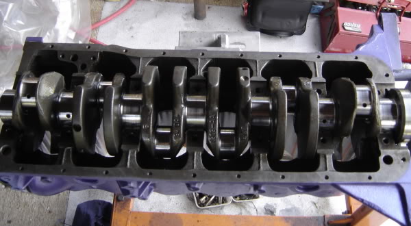
Heath, your first pick is a red motor type crank the second one is a modified blue/black motor type crank....As im sure you know.
What are your thoughts of the balancing of the blue/black type crank??
Now from my very limited understanding of this there not a proper three plane balance, the counterweights on 1 and 6 are larger than the middle four, but in line with the crank pin. The middle four are smaller than the end two but are offset from the center line of the crank pin, assumably to compensate for the larger weights at the ends....
Now i have no idea why Holden did that instead of just hanging the same amount of weight in the same line as the crank pin on all the throws, but what are your thoughts of them??
All the winging about Holden six cranks has seemed to be based on the early style ones with very little in the way of counterweights...I assumed thats what you were talking about then you went the oddball and threw up a pick of a late model type crank.
Edit, just looked at it again, is that a Ford crank in the second pick?? I thought it was a modified late model type one but the more i look at it the more peculiarities i spot...
Cheers.
Edited by Bomber Watson, 17 June 2011 - 11:41 AM.
#9
Heath
View Garage
-
- Administrators
-
- 18,322 posts
I like cars.
- Name:Heath
- Location:Eastern Suburbs, Melbourne
- Car:Heavily Modified UC Sunbird Hatchback
- Joined: 07-November 05
View Garage
Posted 17 June 2011 - 11:51 AM
lol yes the second one is a Ford crank
I sectioned up a red motor crank (3" stroke, cast iron) and did some static balancing tests on the different parts of it so I have some idea of what they are like
I don't really have an opinion on the later model cranks yet. I'm led to believe that they didn't really solve the problem - it's not like they brought in a revolutionary re-design of what they had, they just tinkered. They're a lot heavier too, which would be alright if they solved all the dramas the early cranks had, but yeah, I dunno. I'd be speculating to go any further
Maybe Mike and Brian could share some thoughts?
Edited by Heath, 17 June 2011 - 12:01 PM.
#10
_Bomber Watson_
_Bomber Watson_
-
- Guests
Posted 17 June 2011 - 11:53 AM
Cool. Now answer my question about the late model cranks 
#11
_powerplus_
_powerplus_
-
- Guests
Posted 17 June 2011 - 08:40 PM
Cool. Now answer my question about the late model cranks
Yes they tried to address the harmonic resonance problem with the full counterweighted blue crankshaft and it is a 40 percent better crankshaft. The problem is they still vibrate at around 5900 - 6300rpm. Like i said we have rectified this with our CNC crank mods somewhat but not totally eliminated the problem. cheers
#12
_Bomber Watson_
_Bomber Watson_
-
- Guests
Posted 17 June 2011 - 10:34 PM
Dont take this the wrong way mate, I dont really know much about all this three plane balancing etc, but i fail to see how taking weight out of a crank that is already really to light for the weight hanging off it at the distance it does will improve the problem???
Do you take more weight off 1 and 6 counterweights than the middle ones? And do you machine the middle ones so that the center of mass is in line to the crank pin??
And if so what does the bob weight end up at, and what type of pistons/rods do you have to run to get it all acceptable? Or do you just fill whats remaining of the counterweights with mallory???
Not trying to be sarcastic, so i apologize if it comes across that way, just curious.
Cheers.
#13
_Mike73_
_Mike73_
-
- Guests
Posted 18 June 2011 - 09:45 PM
Hello again,
The weights of the cranks are 186S & LC XU-1 20kg, 202 HQ & all LJ XU-1 22KG, Blue & black cranks 28KG.
As you can see the last cranks were very heavy and consequently did not slow quickly on decelleration.
I do not have the ( Blue modified )knife edge weight in front of me but could measure one I have in the shed.
Actually if I subtract the 9kg flywheel weight that would make those knife edge cranks 23kg if my maths are any good. ( that would mean they machined 5kg of the blue crank )
The standard Holden & XU-1 flywheel is 10.9 kg till the 14th of August XU-1 when they changed to 9kg for the last 160+.
The crank & flywheel combined weight of most LJ XU-1's were the same except for track cars and the last 160+
weight change effects can be changed in several ways, first by altering individual componets, but also by swapping between lighter and heavier flywheels in relation to the crank.
What I mean by this is what I intend to do with my next build is to use the ( Blue modified ) knife edge crank and the stock Starefire flywheel, this combination will make the Crank flywheel assembly just 1kg heavier than the 73 9/ 2 E Homoligated track car engine.
This set up will have this additional weight at the big end counter weight small diameter which should have a better vibtarion dampering effect than the old red crank ( but I am no expert )
Whereas I could just lighten a flywheel in combination to the old red crank to get the same assembly weight but this would likely have a different effect on vibrations and momentum at the much larger flywheel diameter.

It is also worth bearing in mind the weight of the pressure plate assembly as the standard Holden one is lighter than the XU-1 & 1 tonner one and the after market ones available these days are likely different again.
Mike
The weights of the cranks are 186S & LC XU-1 20kg, 202 HQ & all LJ XU-1 22KG, Blue & black cranks 28KG.
As you can see the last cranks were very heavy and consequently did not slow quickly on decelleration.
I do not have the ( Blue modified )knife edge weight in front of me but could measure one I have in the shed.
Actually if I subtract the 9kg flywheel weight that would make those knife edge cranks 23kg if my maths are any good. ( that would mean they machined 5kg of the blue crank )
The standard Holden & XU-1 flywheel is 10.9 kg till the 14th of August XU-1 when they changed to 9kg for the last 160+.
The crank & flywheel combined weight of most LJ XU-1's were the same except for track cars and the last 160+
weight change effects can be changed in several ways, first by altering individual componets, but also by swapping between lighter and heavier flywheels in relation to the crank.
What I mean by this is what I intend to do with my next build is to use the ( Blue modified ) knife edge crank and the stock Starefire flywheel, this combination will make the Crank flywheel assembly just 1kg heavier than the 73 9/ 2 E Homoligated track car engine.
This set up will have this additional weight at the big end counter weight small diameter which should have a better vibtarion dampering effect than the old red crank ( but I am no expert )
Whereas I could just lighten a flywheel in combination to the old red crank to get the same assembly weight but this would likely have a different effect on vibrations and momentum at the much larger flywheel diameter.
It is also worth bearing in mind the weight of the pressure plate assembly as the standard Holden one is lighter than the XU-1 & 1 tonner one and the after market ones available these days are likely different again.
Mike
#14
_Bomber Watson_
_Bomber Watson_
-
- Guests
Posted 18 June 2011 - 09:54 PM
I dont think when your considering three plane dampening that the flywheel weight has any affect??
Cheers for the info though.
Cheers for the info though.
#15
Heath
View Garage
-
- Administrators
-
- 18,322 posts
I like cars.
- Name:Heath
- Location:Eastern Suburbs, Melbourne
- Car:Heavily Modified UC Sunbird Hatchback
- Joined: 07-November 05
View Garage
Posted 19 June 2011 - 01:43 PM
You're talking about polar moment of inertia but you're measuring mass. With a knife-edged crank it would be radically different even if the mass didn't change much.
#16
_Bomber Watson_
_Bomber Watson_
-
- Guests
Posted 19 June 2011 - 02:11 PM
See, this is why im asking questions.
Explain.
Cheers.
Explain.
Cheers.
#17
rodomo
-

- Members
-
- 18,001 posts
To advertise here, call 13TORANA
- Name:R - O - B Dammit!
- Location:Way out west of Melbourne Awstraylya
- Joined: 10-December 05
Posted 19 June 2011 - 02:54 PM
Here's a pic for those struggling with the terminology, this is moments prior to the event.polar moment of inertia
Attached Files
-
 Polar bears.jpg 114.6K
5 downloads
Polar bears.jpg 114.6K
5 downloads
Edited by rodomo, 19 June 2011 - 02:57 PM.
#18
dattoman
-
- Administrators
-
- 16,473 posts
Do I feel lucky? Well, do ya, punk?
- Name:Neil
- Location:Perth Western Australia
- Car:LX SS , 76 Cadillac , 3 x dattos
- Joined: 04-February 07
Posted 19 June 2011 - 03:04 PM
Should I change the tile to Holden cranks for you ?... since I don't see any discussion about conrods... which is what I came here to read about
#19
Heath
View Garage
-
- Administrators
-
- 18,322 posts
I like cars.
- Name:Heath
- Location:Eastern Suburbs, Melbourne
- Car:Heavily Modified UC Sunbird Hatchback
- Joined: 07-November 05
View Garage
Posted 19 June 2011 - 03:38 PM
lol Rob
If you have a body that has a mass and you want to move it, you apply a force and it accellerates. That's linear motion. The more force you put on, the faster it accellerates, or the less weight it has, the faster it accellerates for the same applied force. F = m . a
But if you have a body and you want to rotate it on an axis (in the case of a crankshaft, flywheel etc that axis is along the mains) the amount of resistance that the body has to accellerating and decellerating in angular velocity (i.e. change in rpm), isn't determined by the mass - it's determined by the 'polar moment of inertia'. It's not like they have nothing to do with each other but they are definitely not the same thing! The moment of inertia is to do with what mass occurs where
If you could find the centre of gravity for a counterweight by itself, the distance between that centre of gravity and the axis that you're spinning on, multiplied by the mass of that counterweight gives you the polar moment of inertia of that part of the crank. I'm trying to not be too technical but this stuff is ridiculous to try and say in complete lamen's terms - they have terminology for a reason hahahaha. Anyway you don't need to 'calculate' it on paper, you could measure it if you wanted to, or you could just be aware of that law of nature, and keep it in the back of your head.
#20
_Bomber Watson_
_Bomber Watson_
-
- Guests
Posted 19 June 2011 - 04:17 PM
More questions...
Was that aimed at my post or at Mike73's post??
Whith our new knowledge, how do we go about calculating how big a counterweight we should have and where it should be??
I assume the polar moment of inertia would be impossible to figure for a conrod/piston assembly because if i understand it correctly it would change continuously? So simply working out the correct size counterweight with a polar moment of inertia that is exactly opposite a piston/rod assembly would be impossible? We already knew that....Just now we know how to say it and sound smart
But even though we cant figure the PMI (sorry got sick of typing it) for a piston/rod i take it we can safely assume that the longer the stroke the higher it will be?
So a longer stroke with all other things equal puts more force on the crank shaft....Which we already knew.
I just keep coming back to my idea that equalizing the weights of the counterweights on a blue/black crank and having them all in line with there appropriate crank pin would solve a fair few problems, would this or would this not make the crank three plane balanced??
And if it had three plane balancing but the counterweights wernt quiet heavy enough for the piston/rod assemblies it would still be better wouldnt it? If all the piston/rod assemblies were the same weights and all the counterweights were the same weights and the weight of each was being forced on the crankshaft 180 apart it would be better than what we have now yes?
Or no??
Sorry Heath im just having trouble working out if your agreeing with what i've been posting or disagreeing.
Im still waiting to hear back from Powerplus, but unless im totally backwards then knife edging the crank in theory shouldn't improve the issue unless it equalized the weights of the counterweights like i outlined in post #12 should it?
Now, this
How do we measure it? How do we measure where the center of gravity of the counterweight occurs and how do we measure the weight of the individual counterweight??
Cheers.
You're talking about polar moment of inertia but you're measuring mass. With a knife-edged crank it would be radically different even if the mass didn't change much.
Was that aimed at my post or at Mike73's post??
Whith our new knowledge, how do we go about calculating how big a counterweight we should have and where it should be??
I assume the polar moment of inertia would be impossible to figure for a conrod/piston assembly because if i understand it correctly it would change continuously? So simply working out the correct size counterweight with a polar moment of inertia that is exactly opposite a piston/rod assembly would be impossible? We already knew that....Just now we know how to say it and sound smart
But even though we cant figure the PMI (sorry got sick of typing it) for a piston/rod i take it we can safely assume that the longer the stroke the higher it will be?
So a longer stroke with all other things equal puts more force on the crank shaft....Which we already knew.
I just keep coming back to my idea that equalizing the weights of the counterweights on a blue/black crank and having them all in line with there appropriate crank pin would solve a fair few problems, would this or would this not make the crank three plane balanced??
And if it had three plane balancing but the counterweights wernt quiet heavy enough for the piston/rod assemblies it would still be better wouldnt it? If all the piston/rod assemblies were the same weights and all the counterweights were the same weights and the weight of each was being forced on the crankshaft 180 apart it would be better than what we have now yes?
Or no??
Sorry Heath im just having trouble working out if your agreeing with what i've been posting or disagreeing.
Im still waiting to hear back from Powerplus, but unless im totally backwards then knife edging the crank in theory shouldn't improve the issue unless it equalized the weights of the counterweights like i outlined in post #12 should it?
Now, this
Anyway you don't need to 'calculate' it on paper, you could measure it if you wanted to, or you could just be aware of that law of nature, and keep it in the back of your head.
How do we measure it? How do we measure where the center of gravity of the counterweight occurs and how do we measure the weight of the individual counterweight??
Cheers.
Edited by Bomber Watson, 19 June 2011 - 04:18 PM.
#21
Heath
View Garage
-
- Administrators
-
- 18,322 posts
I like cars.
- Name:Heath
- Location:Eastern Suburbs, Melbourne
- Car:Heavily Modified UC Sunbird Hatchback
- Joined: 07-November 05
View Garage
Posted 19 June 2011 - 05:03 PM
In short, I can't see how simply knife-edging a crank could be advantageous to the balance. But if you work with it on both sides you may be able to get somewhere.
I need to go for work now so I can't answer anything else - no time. Be back in a few days!
I need to go for work now so I can't answer anything else - no time. Be back in a few days!
#22
_Bomber Watson_
_Bomber Watson_
-
- Guests
Posted 19 June 2011 - 05:14 PM
Pfft, translate need to hit google to find my answers 
JK mate hehe.
Cheers.
JK mate hehe.
Cheers.
#23
_Ozzie Picker_
_Ozzie Picker_
-
- Guests
Posted 19 June 2011 - 05:42 PM
i,ll throw a spanner in the works,
a friend of mine had a lj torana,that was striped of all weight,and his engine man up hear have been building holden 6,s since they were introduced,they are both getting on in age,and hold many secrets.
the engine man has a chassis dyno,and would build engine after engine for many years till they had a engine that took my old mate to winning the australian hill climb championship several times,this would have been about at most 10years ago,i think the head was ervin,webbers,but one thing that always stuck in my head was the counterweights were taken back along way,as in very small,no weight,i think the idea came from formula 1 cars.
don,t quote me but talk was 340hp or something like that
the red car is the one i,m talking about,and was sold about 4 years ago,and now races open wheeler
#24
_powerplus_
_powerplus_
-
- Guests
Posted 19 June 2011 - 08:59 PM
Hi guys, like i said earlier we have been experimenting with third plane analysis balancing. It is a fairly new software and does a better job of isolating and identifying force vectors . This enables us to balance more accurately and sometimes with minimal holes to be drilled or weight to be added.We can pinpoint exact positions in the crankshaft. With the 202 counterweighted cnc knifedged crankshaft we play around with no 6 and 2 counterweights sometimes adding a counterweight when required. Every crankshaft requires different balancing techniques . We guard this process pretty well as it is our living after all, i remove the exact amount of weight required for the application.
example
Speedway engines we try and match the drivers driving style. A guy that hugs the pole line gets a superlight crankshaft where a guy that runs the outside (near the fence) gets a much heavier crankshaft. We do use a lot of mallory metal in a lot of our balancing as well. Everyone uses a specific technique to suit their needs when balancing and i am sure everyone has their own theory on this subject. We learn something every day. cheers
#25
_Bomber Watson_
_Bomber Watson_
-
- Guests
Posted 19 June 2011 - 10:26 PM
Fair enough mate.
So basically, yes, what i said.
Cheers.
So basically, yes, what i said.
Cheers.


1 user(s) are reading this topic
0 members, 1 guests, 0 anonymous users

