
Hi all
Finally got the new steering rack properly mounted to the cross member tonight, so its at a point where I'm happy that its going to work. So, time to share :-)
First off a disclaimer: this is not a bolt-in proposition! It requires cutting and welding of the cross member among other things. It is designed to meet my specific requirements, I have not even tested it yet. I don't want to discourage anyone from using this information but if you don't know what you are doing then don't do it!
I'm using a Toyota MR2 SW20 (MK2 I believe) steering rack. It is power steer with a 3.2:1 ratio, rear pinion (front mount) without too much excess bulk. Most importantly, it is approximately 620mm between inner joints which is identical to an LX Torana (see this topic for a bit of discussion on the different racks etc). The ratio is not quite as quick as I would like but there is a quick pinion available for the LHD version and its mirror design is available, occasionally a bunch of MR2 guys seem to get together and have a run of RHD ones made, I'd like to get in on that one day if everything pans out. The MR2 tie rod ends are too long but the tie rods themselves work fine with some S14/Maxima tie rod ends and a very slight trim, and reaming of the steering arms to suit the different angle taper.
Photos and more info coming next.

Another power steering alternative
Started by
76lxhatch
, Aug 02 2012 04:23 PM
45 replies to this topic
#2

Posted 02 August 2012 - 04:42 PM
I wish I was one of those people who can keep everything tidy, it would sure make it easier to find tools when you need them. But I'm not, so you'll have to put up with the mess in the background of all my photos... (even some of the photos are out of order so bear with me)
Here is the MR2 rack in standard form:

You'll notice that the lines to the rack cylinder come out right about where the engine mount is, and the return to the pump is a big fitting on the bottom. Luckily this is one of those racks where the rotary valve can be turned and it fits better spun round 180 degrees. It also has a hydraulic connection on top which would foul the sump, no big deal to move that.
Now from the start I decided that if I was going to cut the cross member at all I may as well do it right and mount the rack in the best possible position. So, out with the grinder and welder!
I moved the front section back approx 10mm

made a bit of room for the rotary valve and lines (you can see the lines altered and the rotary valve turned 180 degrees here)


Here is the MR2 rack in standard form:
You'll notice that the lines to the rack cylinder come out right about where the engine mount is, and the return to the pump is a big fitting on the bottom. Luckily this is one of those racks where the rotary valve can be turned and it fits better spun round 180 degrees. It also has a hydraulic connection on top which would foul the sump, no big deal to move that.
Now from the start I decided that if I was going to cut the cross member at all I may as well do it right and mount the rack in the best possible position. So, out with the grinder and welder!
I moved the front section back approx 10mm
made a bit of room for the rotary valve and lines (you can see the lines altered and the rotary valve turned 180 degrees here)
Edited by 76lxhatch, 21 July 2017 - 10:36 PM.
#3
Posted 02 August 2012 - 04:51 PM
Now before getting too carried away with the new rack I had to take some bump steer measurements with the old one. About here is where I discovered that the UC rack is slightly wider than the LX one (see topic linked in my first post above) but at the end of the day it didn't make a lot of difference.
So I assembled an upper and lower arm destined for the 4 door (new ball joints and bushes) using a stack of shims the same as what I currently have in the hatch - approx 4 degrees of positive caster, 1 to 1.5 degrees of negative camber. The upper arms are mounted in the lower position. All measurements taken at zero toe. My method looks a bit crude but it works really well and makes it easy to see small variances.
I strapped a laser pointer to the stub axle

and placed a sheet of fine graph paper a set distance away from the bottom ball joint (hydraulic press makes a good stand)

With a threaded rod through the shock mount I wound the suspension from full droop to full compression (in fact more than that as the shock and spring won't allow quite so much travel) in fixed increments. At each stop I put a dot on the graph paper in the position on top of the laser dot. Repeated a couple of times to ensure repeatability and accuracy with no hassles, did a couple of comparisons for interest's sake too. End result is no more than 2mm bump steer throughout normal travel with the UC steering arms, with a nice curve centred around ride height:

This is what I wanted to at least match, no point in making it steer worse!
So I assembled an upper and lower arm destined for the 4 door (new ball joints and bushes) using a stack of shims the same as what I currently have in the hatch - approx 4 degrees of positive caster, 1 to 1.5 degrees of negative camber. The upper arms are mounted in the lower position. All measurements taken at zero toe. My method looks a bit crude but it works really well and makes it easy to see small variances.
I strapped a laser pointer to the stub axle
and placed a sheet of fine graph paper a set distance away from the bottom ball joint (hydraulic press makes a good stand)
With a threaded rod through the shock mount I wound the suspension from full droop to full compression (in fact more than that as the shock and spring won't allow quite so much travel) in fixed increments. At each stop I put a dot on the graph paper in the position on top of the laser dot. Repeated a couple of times to ensure repeatability and accuracy with no hassles, did a couple of comparisons for interest's sake too. End result is no more than 2mm bump steer throughout normal travel with the UC steering arms, with a nice curve centred around ride height:
This is what I wanted to at least match, no point in making it steer worse!
Edited by 76lxhatch, 21 July 2017 - 10:36 PM.
#4
Posted 02 August 2012 - 05:02 PM
With that sorted I had to mount up the MR2 rack and measure how it affected bump steer. I did a bit of late night searching on the web to find some tie rod ends and came up with the Nissan ones as above. I was hoping that they were the same taper as the Torana ones (same basic OD) but it turned out they're not. Never mind, with the rack being slightly narrower than the UC one it was of benefit to lower the outer end slightly to compensate (also allowing the rack to sit slightly lower for best clearance), reaming the arms to suit achieved this. As I also mentioned above a slight trim in length was required too, still plenty of thread left.

You can see my silly drawings on bits of tape on the cross member, it occurred to me that was the wrong way to go about it so I made a jig that mounts over the original rack and holds it by the rack shaft itself

can't stuff it up this way!

Removed the rack shaft from the MR2 assembly and mounted it in the jig for some bump steer measurements

I don't have another pretty graph but after some experimenting with shimming the rack in the jig I found equivalent bump steer measurements to the UC rack with it around 5mm lower. Its also somewhere between 5 and 10mm further back just to ensure that toe out on turns is as good as it can be (won't make any significant different but at least it can't be worse).
The MR2 rack has the same travel as the Torana one within a couple of mm so lock won't be an issue.
You can see my silly drawings on bits of tape on the cross member, it occurred to me that was the wrong way to go about it so I made a jig that mounts over the original rack and holds it by the rack shaft itself
can't stuff it up this way!
Removed the rack shaft from the MR2 assembly and mounted it in the jig for some bump steer measurements
I don't have another pretty graph but after some experimenting with shimming the rack in the jig I found equivalent bump steer measurements to the UC rack with it around 5mm lower. Its also somewhere between 5 and 10mm further back just to ensure that toe out on turns is as good as it can be (won't make any significant different but at least it can't be worse).
The MR2 rack has the same travel as the Torana one within a couple of mm so lock won't be an issue.
Edited by 76lxhatch, 21 July 2017 - 10:37 PM.
#5
Posted 02 August 2012 - 05:13 PM
With the position sorted it was time to move on to mounting. Using the same jig with the rack assembled I did some basic checks with a spare engine block and sump, it will be tight (when isn't it?) but shouldn't be any issues there. Being power steer the housing is larger in diameter but it also appears a bit higher than normal as the cross member trimming removed a bit of height at the very front.
Here you can also see where I've moved the connection for the driver side hydraulic feed from the top to the front. The edge of the sump on the driver side sits right at the edge of the mounting strap position, so I rounded this edge on the housing just in case

You can also see above that I've removed the bottom brace for the driver side engine mount, a new piece will go back on a slightly different angle once I'm done

Just enough room is plenty

The angle of the input shaft matches the Torana one, although it is a little shorter. I have a pair of unis with intermediate shaft off a Corolla (I think) that suit the rack and will suit the steering column with some minor tweaks and a larger cotter pin. Clearance around the extractors may be an issue but I don't think any more than the normal Torana unis - I tried mocking it up with a head when I was testing sump clearance but the spare extractors are completely different to what I have in the car (I think they came out of a Commodore, could be a problem when I go to fit them to the 4 door!)
Here you can also see where I've moved the connection for the driver side hydraulic feed from the top to the front. The edge of the sump on the driver side sits right at the edge of the mounting strap position, so I rounded this edge on the housing just in case
You can also see above that I've removed the bottom brace for the driver side engine mount, a new piece will go back on a slightly different angle once I'm done
Just enough room is plenty
The angle of the input shaft matches the Torana one, although it is a little shorter. I have a pair of unis with intermediate shaft off a Corolla (I think) that suit the rack and will suit the steering column with some minor tweaks and a larger cotter pin. Clearance around the extractors may be an issue but I don't think any more than the normal Torana unis - I tried mocking it up with a head when I was testing sump clearance but the spare extractors are completely different to what I have in the car (I think they came out of a Commodore, could be a problem when I go to fit them to the 4 door!)
Edited by 76lxhatch, 21 July 2017 - 10:37 PM.
#6
Posted 02 August 2012 - 05:27 PM
The mounts for the rack housing are a clamp style similar to many Japanese cars, the driver side one is squared off on the bottom to hold the correct angle and the passenger side just goes around the rack cylinder. I didn't have the original brackets and couldn't see any point in using the bushes, so it is solid mounted.
Space on the driver side in particular is tight and I didn't want anything sticking up above the cross member or rack housing. So on that side the bottom half of the bracket has threaded tubes welded into it flush with the ends and the shape of the top piece allows a cap screw on top that doesn't get in the way. The passenger side is just a two piece bracket with captive nuts, all the brackets are made out of solid steel bar shaped to suit (which took some time!)
I don't seem to have any in progress photos of this bit unfortunately. I made a reasonably solid mounting frame that bolts to the original mounting holes in the cross member, and bolted the brackets around the rack housing with it still held in the jig from above with the mounting frame attached. Then it was simply a matter of some good solid tacks to join the mounting brackets and the frame together with the rack held in correct position by the jig. Finish welding things up, check that the heat hasn't moved anything, and the rack now mounts to the cross member.


(there is almost 1mm of clearance there, not that it needs any)

It all still needs to be cleaned up and painted yet (cross member included)
The plan at this stage is to put a VL pump on the passenger side of the engine, so the feed line will come over the front and run along the bottom of the mounting frame. The return line goes up behind the engine mount and will run along the chassis rail around the front of the radiator and back up the passenger side to give a bit of cooling.
And that brings us up to date. Still a bit more work yet but hopefully the most difficult parts are done now.
Space on the driver side in particular is tight and I didn't want anything sticking up above the cross member or rack housing. So on that side the bottom half of the bracket has threaded tubes welded into it flush with the ends and the shape of the top piece allows a cap screw on top that doesn't get in the way. The passenger side is just a two piece bracket with captive nuts, all the brackets are made out of solid steel bar shaped to suit (which took some time!)
I don't seem to have any in progress photos of this bit unfortunately. I made a reasonably solid mounting frame that bolts to the original mounting holes in the cross member, and bolted the brackets around the rack housing with it still held in the jig from above with the mounting frame attached. Then it was simply a matter of some good solid tacks to join the mounting brackets and the frame together with the rack held in correct position by the jig. Finish welding things up, check that the heat hasn't moved anything, and the rack now mounts to the cross member.
(there is almost 1mm of clearance there, not that it needs any)
It all still needs to be cleaned up and painted yet (cross member included)
The plan at this stage is to put a VL pump on the passenger side of the engine, so the feed line will come over the front and run along the bottom of the mounting frame. The return line goes up behind the engine mount and will run along the chassis rail around the front of the radiator and back up the passenger side to give a bit of cooling.
And that brings us up to date. Still a bit more work yet but hopefully the most difficult parts are done now.
Edited by 76lxhatch, 21 July 2017 - 10:37 PM.
#7
_cruiza_
_cruiza_
-

- Guests
Posted 02 August 2012 - 05:58 PM
great ideas and good work, thanks for sharing
#8
UCgazman
-

- Members
-

- 1,342 posts
UC's FTW!
- Name:Garth
- Location:Perth
- Car:UC S̶u̶n̶b̶i̶r̶d̶ 5000!
- Joined: 04-August 11
Posted 02 August 2012 - 06:12 PM
Nice work! 
Just fyi, the VL pump wont fit if you're running a standard efi manifold (been there, done that), carby is no prob but.
Just fyi, the VL pump wont fit if you're running a standard efi manifold (been there, done that), carby is no prob but.
#9
Posted 02 August 2012 - 06:45 PM
Haha well that's the next trick, working on an injection conversion but definitely staying with the early heads. Also I'm talking about a 6 cyl VL pump so I'm going to have to make a bracket anyway. Got a VK 6 cyl pump which is very similar or a V8 one as different options if I can make them work better but want something small that I can mount reasonably far back so I can run a V belt behind the gilmer pulley...
#10
UCgazman
-
- Members
-
- 1,342 posts
UC's FTW!
- Name:Garth
- Location:Perth
- Car:UC S̶u̶n̶b̶i̶r̶d̶ 5000!
- Joined: 04-August 11
Posted 02 August 2012 - 07:22 PM
Ahh well the V8 VL pump is the one I had trouble with, it looks like it'll work until you put the throttle body on... doh! I modded the bracket a little and went with a VK 6cyl pump in the end, should work well.
#11
axistr
 View Garage
-

- Members
-
- 1,169 posts
Forum Fixture
- Location:North west sydney
- Joined: 19-November 05
View Garage
Posted 02 August 2012 - 08:30 PM
Well done Neil, It just takes lots of thinking. I spent around 10 hours of thinking for 5 minutes of constructive work. But you will get there in the end.
#12
Posted 02 August 2012 - 09:09 PM
Who's Neil?
That sounds about right, 10 hours (it might be a stretch to call it all 'thinking' time) for 5 minutes of productivity. I guess its kind of like the whole "measure twice, cut once" philosophy though - it also helps to poach ideas from someone who has worked through similar issues before (thanks)!
That sounds about right, 10 hours (it might be a stretch to call it all 'thinking' time) for 5 minutes of productivity. I guess its kind of like the whole "measure twice, cut once" philosophy though - it also helps to poach ideas from someone who has worked through similar issues before (thanks)!
#13
wot179
-

- Members
-
- 6,784 posts
Green Eggs and Spam
- Name:Jesus Bloody Christ
- Location:Sunny Santa Maria
- Car:Goon
- Joined: 06-February 09
Posted 02 August 2012 - 11:52 PM
I love this type of thread.
Thanks for going to the trouble of starting it.
Great stuff.
Thanks for going to the trouble of starting it.
Great stuff.
#14
dattoman
-
- Administrators
-
- 16,471 posts
Do I feel lucky? Well, do ya, punk?
- Name:Neil
- Location:Perth Western Australia
- Car:LX SS , 76 Cadillac , 3 x dattos
- Joined: 04-February 07
Posted 03 August 2012 - 12:40 AM
I heard a rumour that a certain HQ was getting a power steering setup
An electric one... no pump ... standard non power box
Maybe the person can add more ideas to this thread if thats OK as another option
HQ column being similar to Torana
An electric one... no pump ... standard non power box
Maybe the person can add more ideas to this thread if thats OK as another option
HQ column being similar to Torana
#15
Posted 03 August 2012 - 07:19 AM
That would be interesting to see. I was talking to a guy at the last Rangiora show who was putting a big block in a Torana, he had installed some sort of electric assist unit which I think also improved the ratio. From what I could gather he'd actually replaced the bottom part of the column with this unit so it would have been inside the firewall, which makes sense as there's not much room in the engine bay.
#16
axistr
View Garage
-
- Members
-
- 1,169 posts
Forum Fixture
- Location:North west sydney
- Joined: 19-November 05
View Garage
Posted 03 August 2012 - 09:20 AM
Sorry 76lxhatch, I had a brain fade I thought you name was Neil for some reason. I also thought some MR2s come from factory with electric power steering pumps. I have never worked on one but the mechanic in the unit across the road was working on one and mentioned they were electric.
That's what it's all about here on the forum trying to help others with their projects. I am no natural it take me lots of time thinking, trial & rethinking to sort it all out.
Like you I am to fussy just to make it work it has to be better than factory or don't bother for me.
That's what it's all about here on the forum trying to help others with their projects. I am no natural it take me lots of time thinking, trial & rethinking to sort it all out.
Like you I am to fussy just to make it work it has to be better than factory or don't bother for me.
#17
orangeLJ
-

- Members
-
- 10,259 posts
Yes, yes I do post alot!
- Joined: 02-May 06
Posted 03 August 2012 - 09:28 AM
MR2 (SW2 though from memory) and a heap of late model japanese cars (present day) run electric power steer pumps.
To me, if the electricals can match, it is a GREAT idea and allows for the pump to be mounted in a multitude of places.
To me, if the electricals can match, it is a GREAT idea and allows for the pump to be mounted in a multitude of places.
#18
yel327
-

- Members
-
- 13,088 posts
Oh My, Don't you post alot
- Joined: 10-February 08
Posted 03 August 2012 - 10:03 AM
I reckon you should get the whole setup passed by an Automotive Engineer, you've done all the bump steer and calcs, he'd just have to approve the setup. And then maybe make yourself a little earn by selling modified crossmembers or whole setups for peoples projects. Just a thought, it may not be your cup of tea.
Also, have a look at power steer pumps on GenIII's. Might not work, but with the right adapter bracket it might. Remote reservoir might help, and they are serpentine belt driven.
Also, have a look at power steer pumps on GenIII's. Might not work, but with the right adapter bracket it might. Remote reservoir might help, and they are serpentine belt driven.
#19
ls2lxhatch
-
- Members
-
- 5,332 posts
- Location:Perth
- Car:LX Hatch
- Joined: 29-May 06
Posted 03 August 2012 - 10:12 AM
#20
Posted 03 August 2012 - 11:30 AM
Yeah the MR2 pump is electric and I believe variable pressure (might be ECU controlled in standard form?), guys want them for WRXs and all sorts of things. Personally I don't see the point as its a reasonably big unit that still has to be mounted somewhere and draws a lot of juice, plus they're expensive since they're sought after. The rack itself is just a normal hydraulic assist so any pump will do.
I've tried to document the appropriate parts of the conversion both from an engineering perspective as I want it certified for road use, and in such a way that it can be replicated without too much hassle. I still have the jig which allows me to position a rack correctly on the cross member too, but there is a lot of time and manual work involved in modifying the cross member - I didn't create any templates or such and the shape around the rack head just came from bits and pieces I had lying around. It is very handy that Toranas have a removable cross member when it comes to this stuff so perhaps an exchange type kit could be possible with a better process to make it financially viable but then I don't have any welding or engineering qualifications either...
The pump is unlikely to be a problem, those are just the options I have in the parts pile, it'll work out one way or the other. So far the rack cost me $80 and the new tie rod ends another $80. Still have to buy some new boots, will need a hydraulic fitting and probably a V belt. Plus the welding and grinding consumables of course, and all the time! I love the hot rodding idea of reusing and re-purposing, not often that it actually works though!
#21
Posted 04 August 2012 - 11:17 AM
Sat the cross member on top of the 4 door on the rotisserie (I'm going to miss having it available for mockup purposes when I finally make some progress with it!) and fitted a steering column so I could sort out the intermediate shaft. Turns out that the one I have is the perfect length so the only mods to it are the pin for the steering column end and welding the bottom uni to the splined shaft instead of clamping it, to gain a bit of extractor clearance (fingers crossed on that front).

As an added bonus these unis are like new with no play whatsoever :-)
The rack end is twenty-something spline and can go on any angle so it won't be a hassle getting everything lined up either.
As an added bonus these unis are like new with no play whatsoever :-)
The rack end is twenty-something spline and can go on any angle so it won't be a hassle getting everything lined up either.
Edited by 76lxhatch, 21 July 2017 - 10:38 PM.
#22
Posted 12 August 2012 - 11:56 AM
Set up a crank pulley, just cut the front off a standard twin V belt one (the front had been bent anyway) and with a slight trim the toothed belt pulley sits inside it nicely and there's just enough length in the balancer spigot to locate them both

Edited by 76lxhatch, 21 July 2017 - 10:38 PM.
#23
Posted 14 August 2012 - 09:35 AM
Swapped a suitable pulley onto the power steering pump, this shows roughly where I'm hoping to mount it:

With a bit of luck I can make a bracket to hang it off the front of the passenger side head. Remote reservoir could probably go anywhere but will likely end up on top of the pump, shouldn't need a very big one if I add enough volume in the return cooling loop.
With a bit of luck I can make a bracket to hang it off the front of the passenger side head. Remote reservoir could probably go anywhere but will likely end up on top of the pump, shouldn't need a very big one if I add enough volume in the return cooling loop.
Edited by 76lxhatch, 21 July 2017 - 10:38 PM.
#24
axistr
View Garage
-
- Members
-
- 1,169 posts
Forum Fixture
- Location:North west sydney
- Joined: 19-November 05
View Garage
Posted 15 August 2012 - 07:07 PM
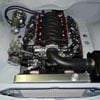
why not just use a VL v8 pump and bracket. fitted this one up a few years ago with Gilmor drive
 139 - Copy.JPG 366.76K
6 downloads
139 - Copy.JPG 366.76K
6 downloads
139 - Copy.JPG 366.76K
6 downloads
#25
Posted 15 August 2012 - 09:30 PM
I don't have the proper power steering pulley for the crank that goes with the Gilmer drive setup and they are very expensive, just trying to make do with what I have for now. I reckon it will work and I quite like the idea of tucking it away down low, but can always fall back on the tried and true setup if need be.
Wow I thought my engine looked grotty when I first posted the pic, compared to that it looks absolutely awful!
Wow I thought my engine looked grotty when I first posted the pic, compared to that it looks absolutely awful!


0 user(s) are reading this topic
0 members, 0 guests, 0 anonymous users

