
Spent some time trying to find all the old topics on this but they don't seem to surface on google?
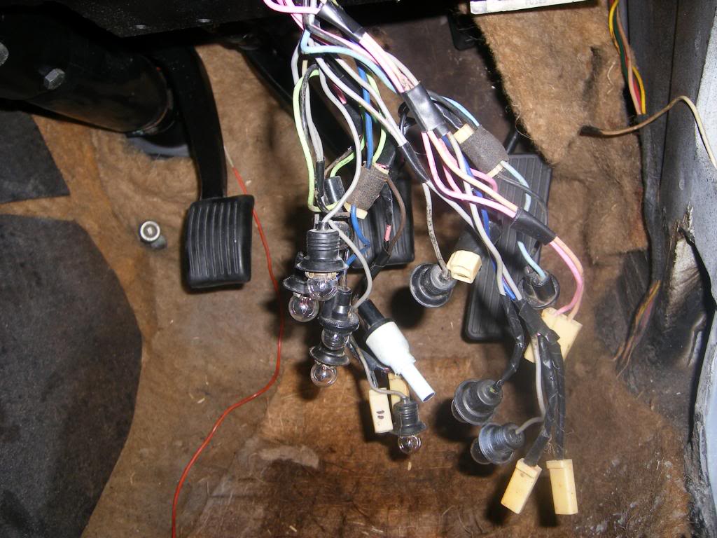
Now I've freshened up my dash and it's ready to go in. All appropriate senders have been installed, so my question is, which wires are which? I need to know the colour for oil and temp, and if I can use the gloves and globe holders from my old dash? I noticed the standard dash has a circuit for which to power the gloves, the XU1 dash doesn't. Does it need new globe holders with terminals for power? Also what are the holes in the back of the small gauges, are they for illumination too?
I'll be looping power for all the gauges, and running a wire to the coil for revs, how do I power the amp meter?
That's about it I think. As it is an LJ dash, need I use the screw in tab brackets from the standard LC dash?
Cheers
Installing XU1 dash.
Started by
_judgelj_
, Nov 28 2013 07:38 PM
45 replies to this topic
#2
 _Skapinad_
_Skapinad_
-

- Guests
Posted 28 November 2013 - 07:49 PM
Isnt there a wiring diagram in the lc shop manual, or am i thinking of something else?
#3
debkar
-
- Members
-

- 911 posts
Forum Fixture
- Location:Townsville QLD
- Car:1971 LC 2 Door
- Joined: 03-January 09
Posted 28 November 2013 - 08:12 PM
Hi Jacob
I did same with my LC that had printed circuit dash.
Used an old HK loom to get the required dash illumination bulbs
I added tachometer cable and used the existing wires for oil and temp.
I didn't wire up the amps gauge
You'll need that odd looking light blue holder as well, hope you have one with your dash
Make sure all is earthed well and I used the LC tabs on lower dash
Regards Simon

#4
hanra
-
- Members
-
- 10,843 posts
Oh My, Don't you post alot
- Name:Brad
- Location:Farrrrrr North Qld
- Car:1975 LH SL/R 5000, 1967 Morris Cooper S, E36 BMW, Toyota Corolla, Isuzu DMax
- Joined: 24-March 11
Posted 28 November 2013 - 08:18 PM
Ammeter wiring

#5
debkar
-
- Members
-
- 911 posts
Forum Fixture
- Location:Townsville QLD
- Car:1971 LC 2 Door
- Joined: 03-January 09
Posted 28 November 2013 - 08:32 PM
Odd blue holder is gen light holder in GTR type dash, should have added that.
#6
_judgelj_
_judgelj_
-
- Guests
Posted 28 November 2013 - 08:50 PM
Re the wiring diagram. I don't think so, and if there is it's not complete. Only one I found is LJ, not 100% it's the same. Simon I do have that blue holder, wasn't sure what it was for. How does the bulb attach to it? As for the other illumination bulbs, I'm guessing I will need to find ones with power going to them? HK onwards did you say? Also, I'll use the LC tabs like you have suggested.
As for the ammeter why can't I just get the power from a power cable?
As for the ammeter why can't I just get the power from a power cable?
#7
hanra
-
- Members
-
- 10,843 posts
Oh My, Don't you post alot
- Name:Brad
- Location:Farrrrrr North Qld
- Car:1975 LH SL/R 5000, 1967 Morris Cooper S, E36 BMW, Toyota Corolla, Isuzu DMax
- Joined: 24-March 11
Posted 28 November 2013 - 08:53 PM
Because it's not a voltmeter.
#9
_threeblindmice_
_threeblindmice_
-
- Guests
Posted 28 November 2013 - 10:43 PM
It had a sports dash , before it was Christine's , check to see if any wires are taped up in the loom . I don't think the mechanic would have snipped them .
#10
S pack
-

- Members
-
- 15,566 posts
Scrivet Counter
- Name:Dave
- Location:Luggage Point
- Car:73 LJ
- Joined: 25-January 10
Posted 29 November 2013 - 12:37 AM
Re the wiring diagram. I don't think so, and if there is it's not complete. Only one I found is LJ, not 100% it's the same. Simon I do have that blue holder, wasn't sure what it was for. How does the bulb attach to it? As for the other illumination bulbs, I'm guessing I will need to find ones with power going to them? HK onwards did you say? Also, I'll use the LC tabs like you have suggested.
As for the ammeter why can't I just get the power from a power cable?
You'll need HT/G instrument illumination bulb holders. HK used bulb holders and a printed circuit board like your LC.
An alternative is to try and find an instrument wiring loom cut for a GTR dash.
#11
Rockoz
-

- Members
-
- 3,973 posts
Lotsa Posts!
- Name:Rob
- Location:Cowra NSW
- Joined: 21-September 08
Posted 29 November 2013 - 08:51 AM
Easy way to do the ammeter.
Find the main Battery feed to the fusebox.
Its the one that comes from the fusible link on the starter.
Cut it at the fusebox and extend it to the ammeter.
Connect it to the -ve terminal on ammeter.
Find another piece of wire the same size and connect one end to the +ve terminal on the ammeter.
Connect other end to the fusebox where you cut the first wire.
Solder and heatshrink the joins.
#12
debkar
-
- Members
-
- 911 posts
Forum Fixture
- Location:Townsville QLD
- Car:1971 LC 2 Door
- Joined: 03-January 09
Posted 29 November 2013 - 01:04 PM
Sorry Jacob , Dave is correct loom is HG
You'll need HT/G instrument illumination bulb holders. HK used bulb holders and a printed circuit board like your LC.
An alternative is to try and find an instrument wiring loom cut for a GTR dash.
Re the wiring diagram. I don't think so, and if there is it's not complete. Only one I found is LJ, not 100% it's the same. Simon I do have that blue holder, wasn't sure what it was for. How does the bulb attach to it? As for the other illumination bulbs, I'm guessing I will need to find ones with power going to them? HK onwards did you say? Also, I'll use the LC tabs like you have suggested.
As for the ammeter why can't I just get the power from a power cable?
Hi Jacob,
The gen light standard size bulb holder clips into the blue holder and the whole unit then fits in the small hole in the back of the GTR type gauge,
#13
_judgelj_
_judgelj_
-
- Guests
Posted 29 November 2013 - 04:40 PM
Ok all very good info, just hope it's not in vein now as Bruce is probably right. Bruce I thought that was the case but the wiring has a standard plug in it and I can see other wires, would probably explain why I have an extra wire from the coil no power must be tacho!
#14
_judgelj_
_judgelj_
-
- Guests
Posted 02 December 2013 - 09:05 PM
Couldnt really find the illusive harness so will start from scratch. Will start by looping all the 12v connections for each gauge. Will most likely drill two holes in each bulb holder, and solder wires to the tangs, this should work? Ill find signal wires for each gauge and attach them. Each corner gauge has a hole in the back, is this for a light? They are round holes without the cutout to twist the holder in. Will the gen warning light fit to the funny blue bulb holder?
Where does the main earth for the dash go? And where do i connect the wiring to load the alternator if i dont use the ammeter gauge?
Cheers
Edited by judgelj, 02 December 2013 - 09:06 PM.
#15
Rockoz
-
- Members
-
- 3,973 posts
Lotsa Posts!
- Name:Rob
- Location:Cowra NSW
- Joined: 21-September 08
Posted 02 December 2013 - 09:52 PM
If I remember correctly the earth for the dash screws to the metal directly behind.
With the ammeter you will still have the globe to excite the alternator.
The main wire from the alternator goes to the battery.
Then off the starter motor a wire goes up to feed the ignition switch and fuse box. It should go through a fusible link from the starter motor.
#16
_judgelj_
_judgelj_
-
- Guests
Posted 02 December 2013 - 10:11 PM
Im a touch confused. Do you know which wire in the standard dash loom is to load the alternator?
Cheers
Cheers
#17
Rockoz
-
- Members
-
- 3,973 posts
Lotsa Posts!
- Name:Rob
- Location:Cowra NSW
- Joined: 21-September 08
Posted 02 December 2013 - 11:39 PM
To excite the alternator pretty sure its a brown wire that runs from the chg globe to the ind terminal on the alternator.
If you have external regulator it also goes there. The other side of the globe goes to an ignition feed.
#18
_judgelj_
_judgelj_
-
- Guests
Posted 07 December 2013 - 08:54 PM
Ok so a few questions. Do I use the wire that runs from the spade terminal of the alternator as the earth for the GEN globe, and 12v for the positive? Is that right?
Also, how can I identify the fusible link wire at the fuse panel? How to I wire in the brake warning switch? Do I connect the wire straight to the brake light bulb, has it got power?
Cheers
Also, how can I identify the fusible link wire at the fuse panel? How to I wire in the brake warning switch? Do I connect the wire straight to the brake light bulb, has it got power?
Cheers
#19
_hutch_
_hutch_
-
- Guests
Posted 08 December 2013 - 06:24 AM
Probably start an argument here but, the best way to wire up the ammeter is to cut the main power feed at the starter motor after the fusible link,now get about 4 meters of 6 mm twin sheathed cable from Bursons,discard the wire that goes from the alternator output to battery positive on the battery.now strip enough off the red cable out of the twin sheathed cable to connect the alt output to the cable runs back into the cabin.
Next step is to connect the ammeter, take the remaking piece of twin sheathed cable connect the black cable to the alt /power feed connection you made earlier,the red cable connects to the fusible link,all that remains is to connect the ammeter and it's done,this basically how it's done factory and ya not working under the dash,as far as the indicator light goes doesn't really matter what it is so long as both terminals are insulated from earth as the globe gets an earth through the alt to excite it as you stated.
Regards Phillip
#20
_judgelj_
_judgelj_
-
- Guests
Posted 08 December 2013 - 12:19 PM
Thanks Phillip. Is 3/4mm wire ok if I was to splice into the main feed under the dash and extend it?
So the alternator feed is an earth, which means the other wire should be 12v, and definitely shielded from other earth as the holder is plastic. Is this right?
What about the break warning light? Diagram shows two wires connected, one is the brake fail wire, and the other is hand brake wire. How can I connect these two a bulb holder that is earthed to the dash casing? Or do I have to use a bulb holder with two wires?
#21
S pack
-
- Members
-
- 15,566 posts
Scrivet Counter
- Name:Dave
- Location:Luggage Point
- Car:73 LJ
- Joined: 25-January 10
Posted 08 December 2013 - 12:38 PM
Jacob, the brake fail/handbrake warning bulb holder cannot be earthed. The brake fail switch at the brake pipe junction block and the h/brake switch at the h/brake lever provide the earth for the bulb.
#22
_judgelj_
_judgelj_
-
- Guests
Posted 08 December 2013 - 02:39 PM
So what powers the bulb? If I solder another wire into the holder, and join the handbrake switch to one wire, break fail to the other, it won't work will it? Sorry if I'm a bit thick I'm just a bit slow to wrap my head around this stuff.
Everything else is pretty straight forward though. Will be buying a plug too.
Everything else is pretty straight forward though. Will be buying a plug too.
#23
S pack
-
- Members
-
- 15,566 posts
Scrivet Counter
- Name:Dave
- Location:Luggage Point
- Car:73 LJ
- Joined: 25-January 10
Posted 08 December 2013 - 02:55 PM
12v power from the dash instruments to one connecter in the bulb holder and the brake fail switch and h/brake lever switch wires joined together onto the other connector.
#24
_hutch_
_hutch_
-
- Guests
Posted 08 December 2013 - 03:00 PM
you need to use twin sheathed cable, ie a red and a black 6 mm cable in a plastic sheath,not sure on the brake fail light, think it might get a feed from the start circuit
#25
_judgelj_
_judgelj_
-
- Guests
Posted 08 December 2013 - 04:32 PM
Thank you so much, makes perfect sense.
I see your logic now, I went and bought 6mm cable rated at 50amp, all the small stuff is only 10amp or so
I see your logic now, I went and bought 6mm cable rated at 50amp, all the small stuff is only 10amp or so


1 user(s) are reading this topic
0 members, 1 guests, 0 anonymous users

