 watts.jpg 52.54K
1 downloads
Nice work !..are the outer ends of the control arms supposed to be where they are or are they meant to be connected to the chassis rails ?

Posted 22 July 2015 - 02:41 AM
G'day EunUCh, yep there are two ways you can set up a Watts Link, you can either have the pivot attached to the centre of the diff with the arms attached to the chassis (like the factory Fraud setup), OR you can do it the way I have above where the pivot & mount attaches to the chassis and the outer ends of the arms attach to the diff.
If I may borrow a couple of eyepeeler's photos, this is what it looks like on an actual car...
The advantage in doing it this way is less unsprung weight, that is to say, less bulk attached to the actual diff itself.
Sprung weight is anything supported by the car's springs (plus a percentage of the springs themselves and anything else like shocks, control arms, etc. connecting 'sprung' to 'unsprung'), sprung weight can be controlled and therefore tuned.
Unsprung weight is connected directly to the road and therein lies the problem, more mass equals more inertia, more inertia means the unsprung weight resists changes in the road surface.
"Objects in motion tend to stay in motion" - Newton's First Law of Physics
Think of hitting a speed bump at speed, a lighter diff will tend to change vertical direction easier and so follow the contour of the bump, a heavier diff would tend to be thrown into the air by the inertia of its own mass, the aim is to keep the tyre in contact with the road as much as possible.
Posted 22 July 2015 - 07:09 AM
Have you watched Project Binky on Youtube? Celica GT-Four suspension and running gear into a Mini, the guy does a lot of bracketry etc using folded sheet metal (much like factory stuff) rather than simple thicker plate steel like many would. He has less choice with such a small car otherwise its going to kill the weight but he does a good job of it. The videos are reasonably entertaining too.What I'm trying to do is design the strength into the structure rather than the material, if I can use 3mm plate instead of 5mm I've saved 40% of the weight
Posted 22 July 2015 - 09:57 AM
Posted 22 July 2015 - 09:51 PM
Wow, those guys on Project Binky do some nice work, I can't believe I just watched all 9 episodes from start to finish.
How's his discipline making everything from scratch, pretty sure I (and most other people) would just be cutting brackets and strut towers out of the Celica shell to graft into the Mini, but kudos to them, can't wait to see the finished product now!
Posted 23 July 2015 - 07:22 AM
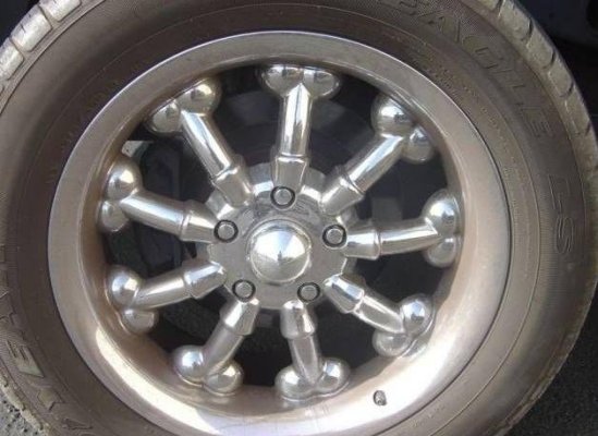
It's actually not too hard to do rims in CAD either as it turns out, this was literally just five minutes work (ignore the pattern, I just threw something in there to break up the boredom)...
 test rim 17x12.5.JPG 71.27K
1 downloads
Hmm, this could get interesting...
(It's probably lucky I don't have a CNC machine ![]() )
)
Posted 23 July 2015 - 07:36 AM

Posted 23 July 2015 - 07:42 AM
Posted 23 July 2015 - 11:06 PM
A little side project...
 SS Grille Emblem_sml.JPG 50.11K
0 downloads
 SS Sticker_sml.JPG 43.08K
1 downloads
I actually did this for wheel caps but couldn't resist doing an emblem and sticker version! ![]()
Posted 25 July 2015 - 10:31 AM
Pulled an all-nighter on this dual-purpose mechanical/hydraulic handbrake design, damn this thing is taxing my brain power!
I've only done the lever so far but that's where most of the magic happens, this is the lever in the straight (cable) position (obviously it won't be see-through IRL)...
 Handbrake Lever in Cable Position.JPG 29.56K
1 downloads
To change to hydraulic mode you trip the latch underneath and the handle then pivots upward to a 45° angle like this...
 Handbrake Lever in Hydraulic Position.JPG 34.72K
1 downloads
As the handle pivots in the centre, two opposing "S" cams cut into the back of the primary lever on each side of the pivot alternately push one of the spring-loaded large pins back through the secondary lever.
In the straight position, the left pin will engage the mechanical cable pull. Also note the two halves of the ratchet release pins line up in this position too.
Changing to hydraulic mode allows the cable pin to retract into the secondary lever and extends the hydraulic pin. Also note the ratchet mechanism is now locked out.
Now I know what you're thinking but there is no 'neutral position', if you somehow managed to pull up the handle somewhere between the two detents you would get both cable and hydraulic braking at the same time. And you physically can't change over unless the handbrake is in the off position because that's the only time both holes line up for the pins to alternate.
To get an idea of the scale, the whole thing is 350mm long, the primary (front) lever is 35mm OD, the secondary lever is 40mm OD and the two large pins are 10mm OD, the clearances will all be tight so I can't see a 10mm solid pin shearing off in a hurry?
The best thing is, for the most part this will look (and act) like an ordinary handbrake lever once it has a boot around it. I may yet redesign that little catch underneath to be a little more discreet, maybe have it covered by the leather boot altogether?
I'd love to keep going and finish the back part but I need to check my eyelids for holes.
Posted 25 July 2015 - 01:08 PM
Seriously, If you put that into production you could probably retire.
I would buy a couple....
Posted 26 July 2015 - 08:02 AM
This is not getting any less complicated I can assure you...
 Handbrake Assy 04.JPG 47K
0 downloads
 Handbrake Assy 05.JPG 40.1K
0 downloads
...but I think it's mostly done, although there's still a couple of little things I need to finish.
The cable lever is the blue, the hydraulic lever the red. The handbrake can operate through 45° which is full stroke on the hydraulic cylinder (1.400"), not sure how far cables normally pull but I set them up for the same travel too, I can change that fairly easily later if it's wrong anyway.
The top of the box sits 150mm off the floor, I could get that down to 100mm if I angle the cylinder but being "in line" (no reservoir, no bleeder) it has to be somewhat self-bleeding, so it would take up a bit of room under the armrest part of a centre console but I doubt that would be any different to any other hydraulic handbrake available?
I still have an adjustable proportioning valve to fit somewhere too, I hope to get it under the inner handle facing forward so just the knob is visible, well still not easily visible, but hopefully easily adjustable?
Posted 26 July 2015 - 08:44 AM
Posted 26 July 2015 - 08:46 AM
I forgot to mention, you may have noticed that I intend to run my handbrake cables through the car as I'll need a full-length console with the top mount of the 3-link rear suspension between the rear seats anyway so I hope to have them follow the upper trailing arm out then run along the axle tubes to the wheels.
I guess the design could be modified to run the cables (or a single cable) through the floor but it would take some thought? And I'm just about all thunk out right now!
P.S. This is the proportioning valve I downloaded...
 Wilwood Prop Valve.JPG 18.57K
0 downloads
...pretty sure it should fit where I want to put it?
I should give a big shout out to Wilwood too, their website has been absolutely invaluable when designing all these floater kits etc., the amount of technical info they make available is unreal.
Everybody bags their product, but if it's even half as good as their tech support I reckon I'd give their gear a go.
EDIT:
Dammit, note to self, I need to (somehow) add a microswitch for the handbrake light on the dash. And I suppose it should only come on when the cable mode is activated too... hmm
Edited by Bigfella237, 26 July 2015 - 08:55 AM.
Posted 26 July 2015 - 09:11 PM
Posted 26 July 2015 - 11:21 PM
Yeah the console is just another thing on the list of 'things to design'. I want it full length front to back; it'll need arm rests front 'n back to clear the handbrake and rear suspension mount; I want to duplicate the touchscreen controls for the stereo (carputer) front & back; I want to separately duct floor and face/air con vents to the rear seats; and the list goes on (and on).
But it's getting to the point where I REALLY need a CAD model of a Torana floor and chassis rails to design stuff off of. I'm more than happy to do the CAD work but I need about a thousand measurements off a body on a rotisserie?
Posted 27 July 2015 - 11:09 AM
Should be near enough detail for the chassis in the plan thats floating around on here to at least get you started.
Would give you base points for the chassis rails.
May be able to get started with it
Posted 27 July 2015 - 02:14 PM
If you mean this one...
 90704_Torrie_Body_Spec_s_122_495lo.jpg 210.86K
1 downloads
...I already tried, but there's just not enough detail.
I could guess a lot of the angles and probably make it "look" okay but I want to design suspension mounting points and exhaust headers and gearbox cross-members and a truck-load of other stuff so it needs to be a little more accurate.
Posted 27 July 2015 - 06:09 PM
Have you tried a scan to cad application?
Posted 27 July 2015 - 07:12 PM
Posted 27 July 2015 - 07:48 PM
Thanks Daz, I'll just have Jeeves warm up the Learjet...
Have you tried a scan to cad application?
Thanks Rob, is that the thing where you take like a thousand photos from every different angle and upload them all to a cloud server, which then generates a 3D model?
Would that work on something so big?
Posted 27 July 2015 - 09:22 PM
Posted 28 July 2015 - 07:04 PM
Was thinking more along the lines of taking a scaled drawing and scanning it into a CAD program.
The alignment drawing would give the basics. The program then works out the lengths and angles etc.
Other drawings could then be scanned and overlaid.
Not perfect but may work well enough to give the basis of what you are after
Posted 28 July 2015 - 08:49 PM
Posted 28 July 2015 - 09:47 PM
0 members, 1 guests, 0 anonymous users