
Hi guys,
I'm in the final stages of developing the shape of the dcoe air box that I've been working on for a while, but what I'm interested in at the moment is if I'm going to have enough clearance between the air box and the underside of the bonnet when the engine torques up.
How much movement should I allow for? I'm assuming that it looks like the engine probably appears to move more than it actually does. I'm thinking that there's probably less than 10mm movement at sudden WOT.
Has anyone out there had any experience in this area?
My plan is to make a fibre glass air box with an aluminium backing plate that bolts directly to the face of the dcoe's and houses the ram tunes inside it. There's a 4“inlet at the front that can house a good quality air filter or possibly be ducted to cold air with an air filter incorporated. I've allowed room for the heater hoses in my design too.
As any of you with dcoe's would know the clearance between the ram tunes and the inner guard is very tight on the rear carb and I've had to come up with a shape to clear this and still be serviceable.
Once the mould for the fibreglass is made I assume that making more of these is reasonably straight forward. So if anyone is interested in one can you put your hand up as an expression of interest and I'll keep this in mind when it's time to go to the fibreglasser.
James

Minimum engine/air box to bonnet clearance
Started by
jd lj
, Nov 19 2016 02:28 PM
68 replies to this topic
#1

jd lj
-
- Members
-

- 2,100 posts
Forum Fixture
- Name:James D
- Location:in the shed
- Car:LJ SVO
- Joined: 03-December 10
Posted 19 November 2016 - 02:28 PM
#2
_LS1 Taxi_
_LS1 Taxi_
-

- Guests
Posted 19 November 2016 - 02:38 PM
Depends on engine mounts.
If you use tuff mounts or similar they don't move at all compared to rubber.
If you use tuff mounts or similar they don't move at all compared to rubber.
#3
dattoman
-
- Administrators
-
- 16,471 posts
Do I feel lucky? Well, do ya, punk?
- Name:Neil
- Location:Perth Western Australia
- Car:LX SS , 76 Cadillac , 3 x dattos
- Joined: 04-February 07
Posted 19 November 2016 - 02:59 PM
Old school trick
Chain the engine
#4
jd lj
-
- Members
-
- 2,100 posts
Forum Fixture
- Name:James D
- Location:in the shed
- Car:LJ SVO
- Joined: 03-December 10
Posted 19 November 2016 - 04:35 PM
I'm going to say no to both of the above. I'm using original engine mounts.
#5
_Bomber Watson_
_Bomber Watson_
-
- Guests
Posted 19 November 2016 - 04:56 PM
Probably a lot more than you would expect, particularly if you dump the clutch at higher rpm.
Unlike the veeates which the carb just moves side to side, we have to contend with them going up and down, and the end of a dcoe is usually a fair way from the rotational centerlien of the engine hence a lot of up and down movement if that makes sense?
Would be best to make it a sliding type setup I recon. MOst the ones you see have some form of slide or flex or something designed into them.
#6
RallyRed
-
- Members
-
- 7,843 posts
Oh My, Don't you post alot
- Name:Col
- Location:NSW
- Car:LC GTR etc
- Joined: 02-October 11
Posted 19 November 2016 - 07:10 PM
Be interested to see what you come up with mate...and apprx Cost.
I guess the clearances to inner guard would depend on the brand of manifold?
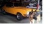
Some pics of mine for your interest...obviously there is a fair bit of moovement as the trumpet hits the gaurd..
Attached Files
-
 20161119_194406sml.jpg 132.89K
5 downloads
20161119_194406sml.jpg 132.89K
5 downloads
-
20161119_194059sml.jpg 234.33K
5 downloads
-
20161119_194524sml.jpg 91.47K
4 downloads
#7
grumpy xu1
-

- Members
-
- 2,809 posts
Lotsa Posts!
- Name:Gary
- Location:Queensland
- Car:lj xu1
- Joined: 01-February 10
Posted 19 November 2016 - 08:47 PM
Hi James, if you have a look at cols photos, you would see wot isn't the bonnet issue it's backing off. Obviously because the engine goes clockwise, you could adjust rear ram tubes up slightly & then loosen engine mounts bolts & rotate the engine slightly clockwise to given clearance of returning of wot. Most important question here is what is your reason for the air box design ? Cold air, hp ect. I think the answer to that could confirm design. Gary.
#8
jd lj
-
- Members
-
- 2,100 posts
Forum Fixture
- Name:James D
- Location:in the shed
- Car:LJ SVO
- Joined: 03-December 10
Posted 20 November 2016 - 05:39 AM
Hi Col,
What manifold are you using on your set up? I'm using a Seton manifold and on the rear ram tube I have 10mm clearance between it and the inner guard with STD ram tubes. However I also have a set of angled tubes which gives me 20mm clearance. Have you considered modifying your tubes by making a cut and bending them up and then rewelding the join or JNT Performance can make custom tubes with a mandrel bend (which I may consider down the track)
With my Seton mm manifolds I have no problems with the ram tubes hitting the inner guard when I back off from WOT.
Grumpy,
The reason for working on this project is so that I can achieve decent filtration which will give engine longevity and a very slight increase in performance in theory (this would be probably too small to notice). Another advantage is that the air box will contain any fumes caused by reversion or from fuel vapours existing via the float bowl vents, I will also have the ability to connect the PCV set up to the backing plate and if I'm keen I can also duct it to cold air in the future.
I currently use s/s wire screen filters which have a rubber lip that slips over the lip of the ram tubes. These filters are not actually very good at filtering fine particles, cause turbulent air flow and make the radius at the end of the tubes ineffective because the rubber lip on the filters covers it up to a certain degree so therefore the ram tubes don't do the job they were designed to do.
#9
RallyRed
-
- Members
-
- 7,843 posts
Oh My, Don't you post alot
- Name:Col
- Location:NSW
- Car:LC GTR etc
- Joined: 02-October 11
Posted 20 November 2016 - 08:54 AM
Hi Col,
What manifold are you using on your set up?
I'm thinking they are 3 individual Redline TK3130 ??
Attached Files
-
Redline TK3130.jpg 142.75K
7 downloads
#10
jd lj
-
- Members
-
- 2,100 posts
Forum Fixture
- Name:James D
- Location:in the shed
- Car:LJ SVO
- Joined: 03-December 10
Posted 20 November 2016 - 02:30 PM
I don't know the part numbers but it looks similar to the warnerford manifolds.
Are your cards 45dcoe152's or 45dcoe53/54/55/56. I remember someone on here had the rt charger dcoe's, but I can't remember if it was you or someone else.
Are your cards 45dcoe152's or 45dcoe53/54/55/56. I remember someone on here had the rt charger dcoe's, but I can't remember if it was you or someone else.
#11
RallyRed
-
- Members
-
- 7,843 posts
Oh My, Don't you post alot
- Name:Col
- Location:NSW
- Car:LC GTR etc
- Joined: 02-October 11
Posted 20 November 2016 - 05:26 PM
I don't know the part numbers but it looks similar to the warnerford manifolds.
Are your cards 45dcoe152's or 45dcoe53/54/55/56. I remember someone on here had the rt charger dcoe's, but I can't remember if it was you or someone else.
45dcoe152.
I guess the purpose of my post was just to show the movement down, ....dont know about up.
Edited by RallyRed, 20 November 2016 - 05:29 PM.
#12
grumpy xu1
-
- Members
-
- 2,809 posts
Lotsa Posts!
- Name:Gary
- Location:Queensland
- Car:lj xu1
- Joined: 01-February 10
Posted 20 November 2016 - 09:38 PM
Well to me mate, you had me when you said good filtration & maybe some hp. Sounds like a sensible and practical post. So apart from the filtration, i guess i would think would a certain shape work better for airflow than another. Is there a possibility that you could make a different tube design and run 3 individual filters like a k&n style ? If you have fb have a look at, psico or cams fabrication whatever he's calling his business. It may give you a direction, cam may answer some questions i don't know. I know him but he does have to make a living. Just a thought that's all hope you come up with a plan mate, Gary.
#13
LC-GTR-1969
 View Garage
-
- Members
-
- 1,162 posts
Shed tinkerer
- Location:New South Wales
- Car:Which one?
- Joined: 09-March 14
View Garage
Posted 25 November 2016 - 05:08 PM
I don't know the part numbers but it looks similar to the warnerford manifolds.
Are your cards 45dcoe152's or 45dcoe53/54/55/56. I remember someone on here had the rt charger dcoe's, but I can't remember if it was you or someone else.
That would be me mate... dcoe55s
#14
jd lj
-
- Members
-
- 2,100 posts
Forum Fixture
- Name:James D
- Location:in the shed
- Car:LJ SVO
- Joined: 03-December 10
Posted 10 December 2016 - 07:38 AM
I did another trial fit and a bit more work on the shape of the air box last weekend and I should have a minimum of 25mm clearance between the bonnet and the air box. I think this should be sufficient space to not have any issues.
I'm going to do another trial fitment again this weekend and I need to decide on a method to attach the outer shell to the alloy backing plate and have a talk to a fibreglass company about producing this.
I'm considering something like 2 or 3 wingnuts halfway up the side of the shell with spacer bolts like xu-1 air filters to secure the outside shell. There'll be a channel at the bottom of the backing plate that the shell clips into with a rubber seal between the two. Another fastening method would be to have 2 or 3 bolts across the top similar to what the cold air boxes from "Boi Performance" have (unfortunately his air boxes won't fit a webered LC/LJ).
#15
_Agent 34_
_Agent 34_
-
- Guests
Posted 12 December 2016 - 07:37 PM
I'm thinking they are 3 individual Redline TK3130 ??
pretty sure col yours are warneford - redline is a copy and then joined into a one piece - funny im about 5 weeks late on a response from cols post !!!
James - can you do a " clip system" where by the bottom channel clicks in and then the top has a latch - like on a boating style - i'll find one and post
Edited by Agent 34, 12 December 2016 - 07:38 PM.
#16
jd lj
-
- Members
-
- 2,100 posts
Forum Fixture
- Name:James D
- Location:in the shed
- Car:LJ SVO
- Joined: 03-December 10
Posted 15 December 2016 - 05:55 PM
I was considering using spring loaded latches (hatch latches I think they are called), but have decided on using 3 bolts to secure the top edge and the bottom sits in a channel which will be sized appropriately to apply enough pressure to the rubber seal.
I took my template to the fibreglasser this week and he was impressed with my woodworking skills, I expect nothing less from my work, but also said that it'll be straight forward to make and he's happy to do it for me.
I have to pay for the mould to be made from my template and then obviously for each air box, this way I own the mould and can get more made if required.
So I've had a couple of late nights in the shed finishing off the template and it's now only needing another sand and a few more coats of paint so that the mould has a nice smooth surface to cast the air boxes in. This will mean that when they come out of the mould they'll have a good surface finish.
James
#17
jd lj
-
- Members
-
- 2,100 posts
Forum Fixture
- Name:James D
- Location:in the shed
- Car:LJ SVO
- Joined: 03-December 10
Posted 15 December 2016 - 06:19 PM
Just out of interest, can anyone with dcoe's in their LC/LJ give me a measurement from the top of the chassis rail to the centre line of the barrels of the rear carb and then I can see if this air box can possibly fit with other manifolds. This may also vary depending on the angles of the manifold faces which should be around 5 degrees.
On my Seton manifolds the measurement from the top of the chassis rail to the centre line of barrel number 5 is approximately 105mm measured at the face of the carb.
On my Seton manifolds the measurement from the top of the chassis rail to the centre line of barrel number 5 is approximately 105mm measured at the face of the carb.
#18
_Agent 34_
_Agent 34_
-
- Guests
Posted 15 December 2016 - 07:00 PM
yep will do over the weekend
see col has the same manifold as me - but his tubes are shorter and the turn down hits the inner guard.
i'll check my measurements but they will be different as the runner lenght is longer
Question - what length runner do you have on the seaton's
Q2 - how long do you think the air box will take in runner lenght
Edited by Agent 34, 15 December 2016 - 07:04 PM.
#19
jd lj
-
- Members
-
- 2,100 posts
Forum Fixture
- Name:James D
- Location:in the shed
- Car:LJ SVO
- Joined: 03-December 10
Posted 30 December 2016 - 07:09 PM
Moving ahead with the air box and I'm just after the opinion of anyone with a bit of engineering experience.
At this stage I have a 3mm thick aluminium backing plate that the shell will attach to with 3 bolts at the top, most likely M6 thread. What I'm considering is will a M6 thread in 3mm aluminium resist being stripped keeping in mind that it only needs to be tightened enough to apply pressure to the rubber seal. The alternative option would be to use a nutsert to bolt into, I need to ensure that these are positioned to avoid interfering with the heater hoses which run behind the top of the backing plate, obviously I can't have any chance of these rubbing through the hoses.
Today I made some prototypes for the new heater hose brackets similar to what Chevrolet were using in the 50's,60's and 70's.
The template for the air box should be at the fibreglasser early next week, I missed him today.
#20
grumpy xu1
-
- Members
-
- 2,809 posts
Lotsa Posts!
- Name:Gary
- Location:Queensland
- Car:lj xu1
- Joined: 01-February 10
Posted 30 December 2016 - 08:55 PM
Hey mate, if was me i would run 1/4" only because it's an imperial car, the finer the thread the stronger the pressure it will hold. Don't run stainless as it will be much harder than the aluminium, just a zinc bolt would work & look factory I'd fit a fibre washer to the fibreglass face, then a flat washer followed by a internal shake proff washer & obviously the bolt. Blackwoods & the like should have imperial bolts, or try fasteners online in the goldcoast. Personally i feel bolts & nuts would be the go rather than tapping the aluminum. You could get the fibreglasser to put in a alloy tube or shape it like the corners of the heater box. If you use stainless steel bolts, lube them with pig fat a block of supa fry at wollies ect for about $5 will do you for years. Hope that helps. Gary.
#21
_duggan208_
_duggan208_
-
- Guests
Posted 31 December 2016 - 01:14 AM
Its good to see that someone else is mad enough to battle with the LC/J airbox. I'm on my 4th attempt, even cut out the inner guard, lowered it about 20mm for clearence. little bit worried about how close the front wheel will come to scraping on the other side of the inner guard under brakes. I'm trying to use the bonnet as the top of the airbox and the backing plate is attached to the throttle bodies and it moves and slides on seals just inside the box which is mounted to the inner guard. I'm certainly no expert but I'm concerned about the pulses, especially with 6 throttle bodies, inside a sealed box so i'm trying 2 Celica ST 204 air filters as a box wall to disipate pulses that might hurt airflow into the ram tubes. Very interested to see how your design workes, a pic is would be great.
regards
#22
jd lj
-
- Members
-
- 2,100 posts
Forum Fixture
- Name:James D
- Location:in the shed
- Car:LJ SVO
- Joined: 03-December 10
Posted 31 December 2016 - 06:41 AM
Thanks for the input guys.
Grumpy, I had considered just using a nut on the back of the backing plate to screw into but in my mind I see using a non fixed nut as something that can easily be dropped or miss placed during service operations.
The idea of a fibre washers between the flat washer and the fibreglass sounds like a good idea.
I'm not too concerned about using a metric or imperial thread as all the fasteners on webers/dcoe's are metric. Your point about using a fine thread to screw into aluminium is one of the differences between dcoe's and dellorto's, dcoe's use fine threads for all their fasteners which are in aluminium and dellorto's don't.
Jon/duggan208, I agree that there is a certain amount of craziness in undertaking or proceeding with this project. Yours is sounding like a creative and complicated design.
The clearance between the ram tubes and inner guard is where the greatest complications lie as the air box has to attach to the backing plate below the height of the inner guard but still be able to be taken on and off.
Have you looked into using ram tubes that kick up at a bit of an angle to gain more clearance with the inner guard.
I've spent most of the year working on this on and off. I couldn't have picked a more hectic year at home to tackle this project but fingers crossed I'm almost there. I'm sure that my friends think I'm mad with the efforts I go to with my projects but also expect nothing less from me. Someone has to raise the bar and set new benchmarks for other to aspire to, lol.
#23
grumpy xu1
-
- Members
-
- 2,809 posts
Lotsa Posts!
- Name:Gary
- Location:Queensland
- Car:lj xu1
- Joined: 01-February 10
Posted 31 December 2016 - 10:14 AM
If you don't fit the fibre washers, the fibre glass gets them little annoying hairline cracks mate. I use them a bit on any little jobs i do on the cars. Gary.
#24
_duggan208_
_duggan208_
-
- Guests
Posted 02 January 2017 - 12:53 AM
Yes i am thinking about cutting the ram tubes and using 6, angled 2 inch airbox pipes and simply hose clamp them together. I suppose that the more clearance around a ram tube the more air it can get in. Actually i think EFI hardware in Victoria make angled ram tubes and air boxes for multi throttle bodies so they are likely to also fit the Webers, but, there's nothing like the challenge of doing it yourself. Raise that benchmark mate.
Regards
#25
jd lj
-
- Members
-
- 2,100 posts
Forum Fixture
- Name:James D
- Location:in the shed
- Car:LJ SVO
- Joined: 03-December 10
Posted 17 March 2017 - 08:07 PM
Well I'm getting very close to completing my air box now. I should say that it may just be completing this phase of its evolution, who knows what lies ahead with this project.
I now have the mould made for the outer shell and the actual outer shell back from the fibreglasser, the backing plate has been cut to shape and a channel welded onto the bottom plus the holes tapped for the outer shell to bolt to.
I used a spare carb body and photocopied it to then transfer the hole positions onto three pieces of MDF to make three individual carb templates. Next I fitted these to the carbs and then glued on two strips of timber to join the three templates to make one. This way all the holes should line up nicely to then transfer them to the alloy backing plate. So I now need to drill out about 21 holes in the backing plate and I'm ready to fit the whole thing to the car.
However my next question is, would there be likely to be any movement of the engine rearwards under certain conditions during driving?
The reason I'm asking is that I probably have less than 10mm clearance between the back of the air box and the heater box when trial fitting with my existing MDF backing plate template. I can probably move everything forward a few more millimetres if necessary but obviously this is better to know before I drill out the alloy backing plate.
What's your thoughts on this guys?


0 user(s) are reading this topic
0 members, 0 guests, 0 anonymous users

